Method and system for toolpath generation

a toolpath and tool technology, applied in the field of manufacturing processes, can solve the problems of cumbersome, cumbersome, and high cost of toolpath generation methods for smd process, and achieve the effect of reducing the number of tools and processes, increasing programming time, and increasing the number of tools

Active Publication Date: 2007-09-27
THE BOEING CO
View PDF18 Cites 28 Cited by
  • Summary
  • Abstract
  • Description
  • Claims
  • Application Information

AI Technical Summary

Problems solved by technology

The current methods of producing toolpaths for the SMD process are highly inefficient as described below.
This adds programming time and is cumbersome.

Method used


Image

  • Method and system for toolpath generation
  • Method and system for toolpath generation
  • Method and system for toolpath generation

Examples


Embodiment Construction

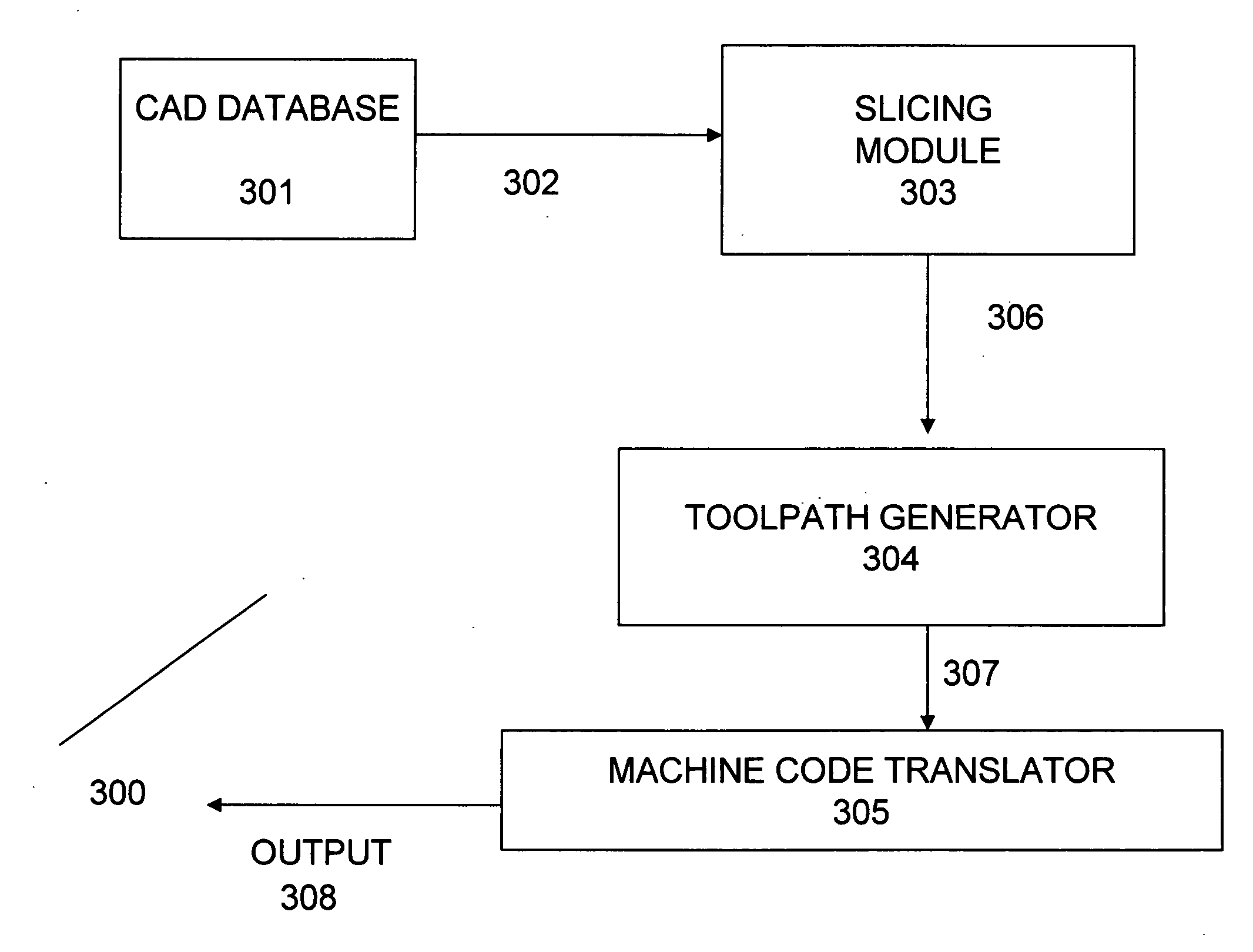
[0018] The present invention provides an automated method / system for generating toolpaths that are used to create three-dimensional products using deposition processes. The system can be implemented in software and executed by a computing system. To facilitate an understanding of the preferred embodiment, the general architecture and operation of a computing system will be described first. The specific process under the preferred embodiment will then be described with reference to the general architecture.

Computing System:

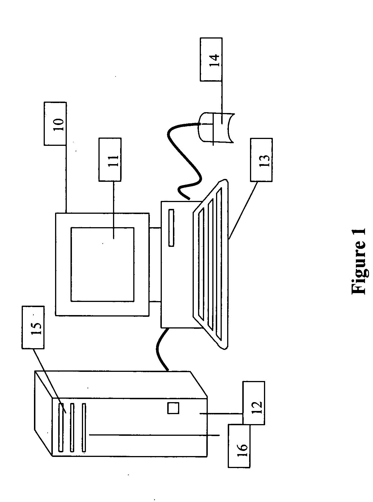
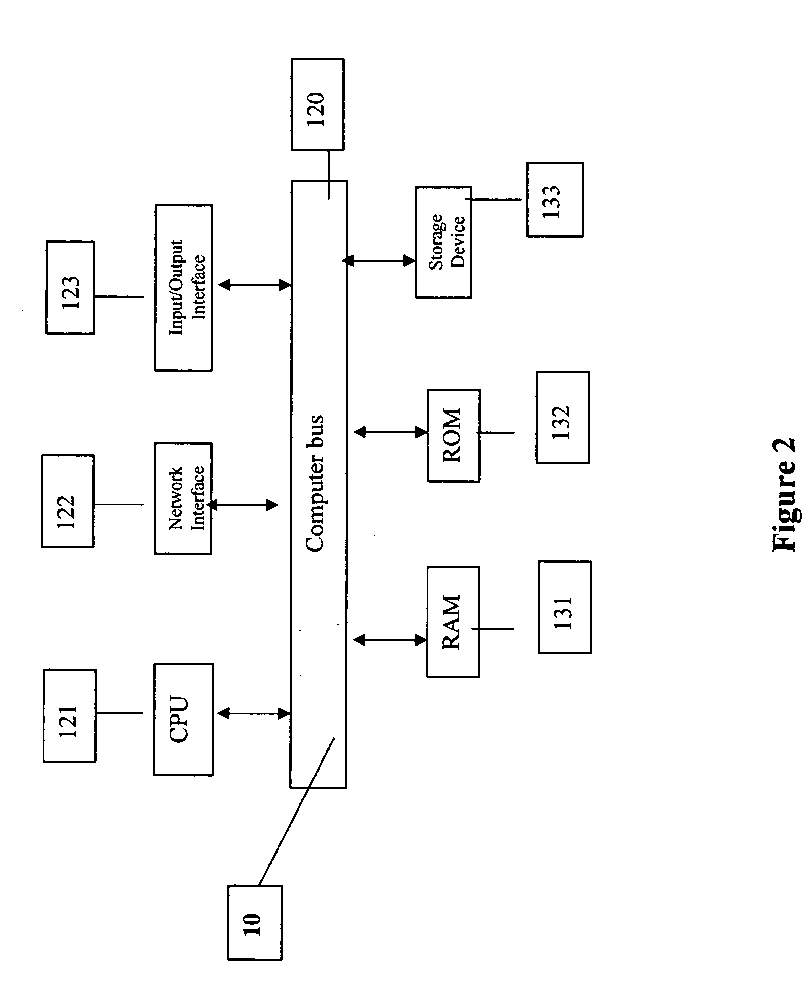
[0019]FIG. 1 is a block diagram of a computing system for executing computer executable process steps according to one aspect of the present invention. FIG. 1 includes a host computer 10 and a monitor 11. Monitor 11 may be a CRT type, a LCD type, or any other type of color or monochrome display.

[0020] Also provided with computer 10 are a keyboard 13 for entering data and user commands, and a pointing device (for example, a mouse) 14 for processing objects displ...


PUM


Abstract

A system and method for toolpath creation is provided. The method includes exporting CAD defined 3-D geometry to a slicing module; slicing the 3-D geometry creating a set of 2-D patterns representing the 3-D geometry; generating vector code from the set of 2-D patterns; and translating the vector code to machine code.

Description

BACKGROUND [0001] 1. Field of Invention [0002] This invention relates generally to manufacturing processes, and more particularly, to automated toolpath generation that can be used in deposition processes. [0003] 2. Background of the Invention [0004] Shaped metal deposition (SMD) is an additive manufacturing method that deposits metal via Gas Tungsten Arc Welding (GTAW) methodically in a manner that generates a 3-D geometry. The current methods of producing toolpaths for the SMD process are highly inefficient as described below. [0005] Traditional CNC toolpath generation (i.e. raw stock is used and the excess material is cut away to get the final product) software is employed and proceeds through several software packages prior to generating useable deposition path codes. Since no supports are used for building complex geometric features in CNC toolpath generation, parts that are deposited in the X-Y plane are rotated or the material feed head is moved to a position other than verti...

Claims


Application Information

Patent Timeline
Patent Type & Authority Applications(United States)
IPC IPC(8): G06F19/00G16Z99/00
CPCG05B19/4099G05B2219/49035G05B2219/49014G05B2219/49013B33Y50/00G16Z99/00
Inventor SLAUGHTER, VICTOR B.HUSKAMP, CHRISTOPHER S.
Owner THE BOEING CO
Why Eureka
Try Eureka