Control unit for a machine

a technology for controlling units and machines, applied in electrical control, program control, instruments, etc., can solve problems such as shortened service life of prime mover or transmission, unauthorized attempts to manipulate application data, and operational safety, and achieve the effect of preventing operation risks

Inactive Publication Date: 2007-09-27
ROBERT BOSCH GMBH
View PDF4 Cites 7 Cited by
  • Summary
  • Abstract
  • Description
  • Claims
  • Application Information

AI Technical Summary

Benefits of technology

[0009] The present invention provides a control unit which prevents the risk of operation using unsuitable application data, i.e., application data that have been manipulated by an unauthorized party, and application data that have been generated by an authorized party but not checked for security.

Problems solved by technology

In particular for control units used in the automotive sector, attempts are often made by unauthorized parties to manipulate application data to, for example, boost the power of a prime mover controlled by the control unit.
Such power boosts, not intended by the vehicle manufacturer, may endanger the operational safety of the vehicle, result in a shortened service life of the prime mover or the transmission, or create problems in registering the vehicle.
However, such an approach does not provide protection in the event that the application process for the control unit operates using application data that have been generated by an authorized party and stored together with matching integrity test information, but which nevertheless specify algorithms or values of operating parameters which do not ensure safe operation of the machine.
Such a situation may occur more easily the greater the number of physical parameters which the control unit must detect or adjust in the machine which it controls and which are correlated with one another, so that for these physical parameters it is not possible to specify any given combination of values by use of the application data.
One disadvantage of this approach, however, is that after the application data have been transmitted to the control unit it is no longer possible to verify at the control unit itself whether such a security check has taken place.
This makes it difficult for the manufacturer of the control unit to demonstrate that a security check has occurred, if the manufacturer becomes liable for damage allegedly caused by the control unit.

Method used


Image

  • Control unit for a machine
  • Control unit for a machine

Examples


Embodiment Construction

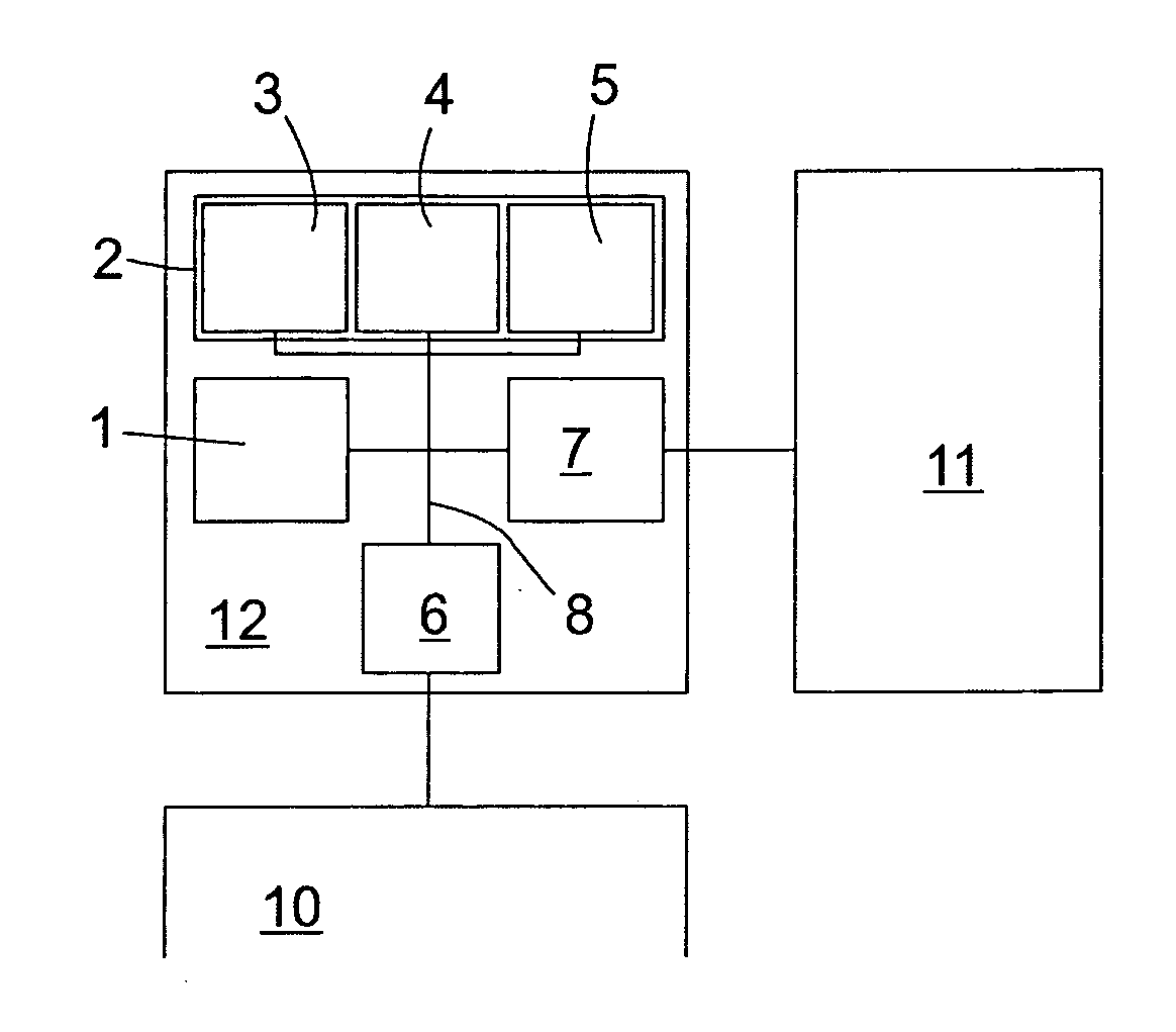
[0026] The control unit, denoted in general by reference numeral 12 in FIG. 1, includes a microprocessor 1; a memory 2 which may be composed of a plurality of components such as a volatile random access memory (RAM) 3, a read-only memory (ROM) 4, and an electrically overwritable read-only memory, in particular a flash memory 5; one or more interfaces for communication with sensors and actuators for a machine 10 to be controlled, denoted collectively as machine interface 6; and a programming interface 7 which is connectable to an external data source such as a host computer 11 or a workstation diagnostic device, which are interconnected by a bus 8.

[0027] As an application example, the case is considered below in which machine 10 is an engine of a motor vehicle, and control unit 12 is an engine controller. An application program is stored in ROM 4 and / or flash 5 which enables microprocessor 1 to control engine 10, for example by adjusting the ignition angle in engine 10 or the fuel m...


PUM


Abstract

A control unit for a machine includes a processor and a memory for program instructions and parameter values. A first portion of the program instructions defines a first process which accesses the parameter values in order to ascertain control information and to transmit same to the machine, and a second portion defines a second process which evaluates the quality of the application data, and either permits or prevents the execution of the first process based on the evaluation results. The second process checks whether the value of at least one first physical parameter specified by the application data is valid and does not permit execution of the first process using these application data unless the value of the parameter has been determined to be valid.

Description

BACKGROUND OF THE INVENTION [0001] 1. Field of the Invention [0002] The present invention relates to a control unit for a machine, e.g., for a prime mover of a motor vehicle. [0003] 2. Description of Related Art [0004] Such a control unit generally includes a processor and a memory for application data, i.e., program instructions and parameter values, the program instructions defining at least one first process, in this context also referred to as an application process, which among other functions accesses the parameter values in order to ascertain control information and transmit same to the machine to control the operation thereof. [0005] In particular for control units used in the automotive sector, attempts are often made by unauthorized parties to manipulate application data to, for example, boost the power of a prime mover controlled by the control unit. Such power boosts, not intended by the vehicle manufacturer, may endanger the operational safety of the vehicle, result in ...

Claims


Application Information

Patent Timeline
Patent Type & Authority Applications(United States)
IPC IPC(8): G06F9/44G06F21/57G06F21/64
CPCF02D41/266G05B19/042G05B2219/23213G05B2219/23215G06F21/64G05B2219/24042G05B2219/24155G05B2219/2637G06F21/57G05B2219/24034
Inventor NEUFELD, MARCHUMMEL, JUERGEN
Owner ROBERT BOSCH GMBH
Why Eureka
Try Eureka