
Visual Recognition Assistance Apparatus for Vehicle

a technology for visual recognition and assistance devices, which is applied in the direction of bumpers, transportation and packaging, and signalling indicators on vehicles, etc., can solve the problems of difficulty in accurately and instantly recognizing distances for vehicle drivers, and achieve the goal of enhancing the accuracy of positional recognition, enhancing the accuracy of pole section position recognition, and facilitating the recognition of pole section positions

Inactive Publication Date: 2007-10-04
HONDA MOTOR CO LTD
View PDF14 Cites 1 Cited by
  • Summary
  • Abstract
  • Description
  • Claims
  • Application Information

AI Technical Summary

Benefits of technology

[0005] In view of the foregoing, it is an object of the present invention to provide an improved visual recognition assistance device for a vehicle which permits accurate and instant positional recognition of a fore end portion of the vehicle.
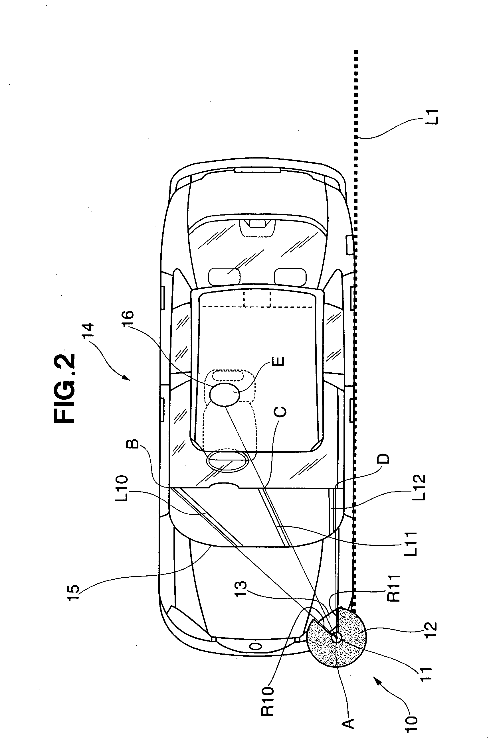
[0011] According to the present invention, the provision of the plate section allows the vehicle driver to perceive or recognize the distal end of the pole section even where the ground surface is not visible. Further, the provision of the pole-section-position indicating portion can even further enhance the accuracy of the pole section position recognition. Furthermore, because the plate section has two sides extending substantially at right angles to each other, and one of the two sides is substantially parallel to the front edge line of the vehicle while the other of the two sides is substantially parallel to the side edge line of the vehicle, the front edge line and side edge line of the vehicle can be recognized with an increased ease, which can even further enhance the accuracy of the positional recognition. Furthermore, with the instrument panel having an upper surface parallel to the ground surface, the pole section position can be recognized with ease on the basis of the plate section and instrument panel. With the additional provision of the guide lines extending or oriented toward the pole section, the accuracy of the pole section position recognition can be even further enhanced. Namely, the present invention allows the driver to perceive the distance to the vehicle corner with an enhanced accuracy, by the provision of the plate section or pole-section-position indicating portion, the guide lines on the instrument panel, etc.

Problems solved by technology

Although the distal end of the corner pole can be visually recognized, it is sometimes difficult for the vehicle driver to accurately and instantly recognize a distance to the corner pole due to loss of the sense of distance as noted above.

Method used


Image

  • Visual Recognition Assistance Apparatus for Vehicle
  • Visual Recognition Assistance Apparatus for Vehicle
  • Visual Recognition Assistance Apparatus for Vehicle

Examples


Embodiment Construction

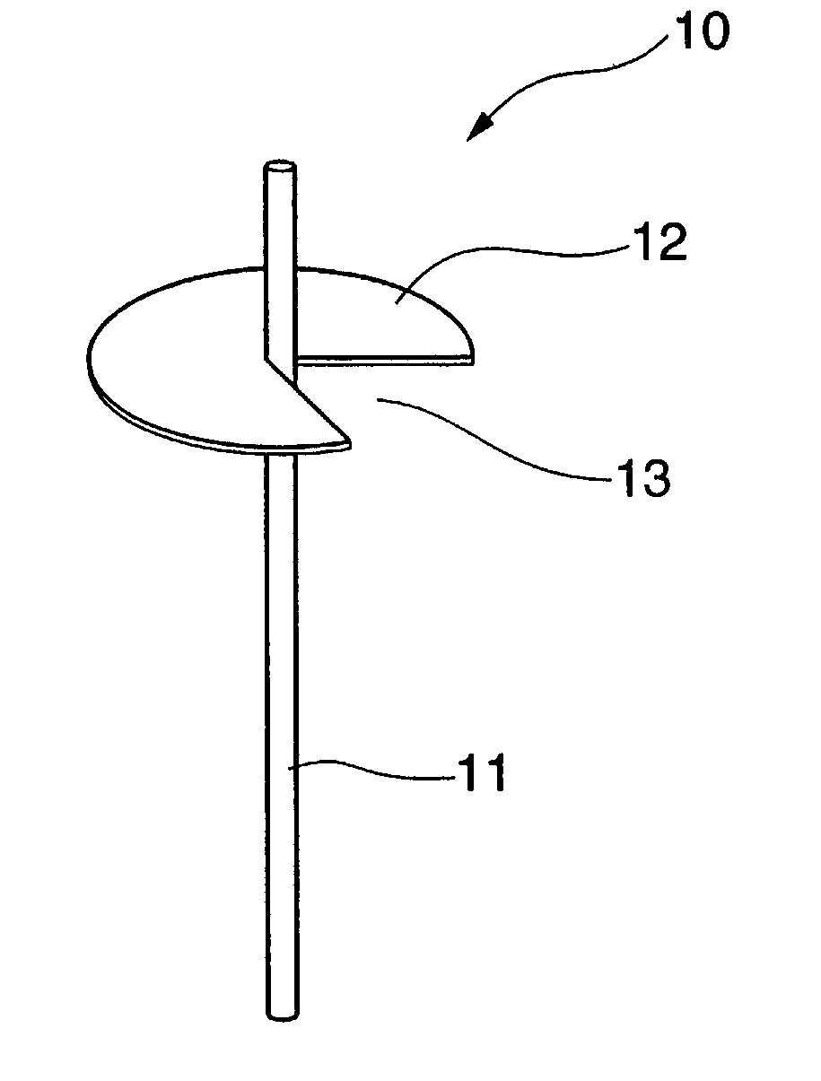
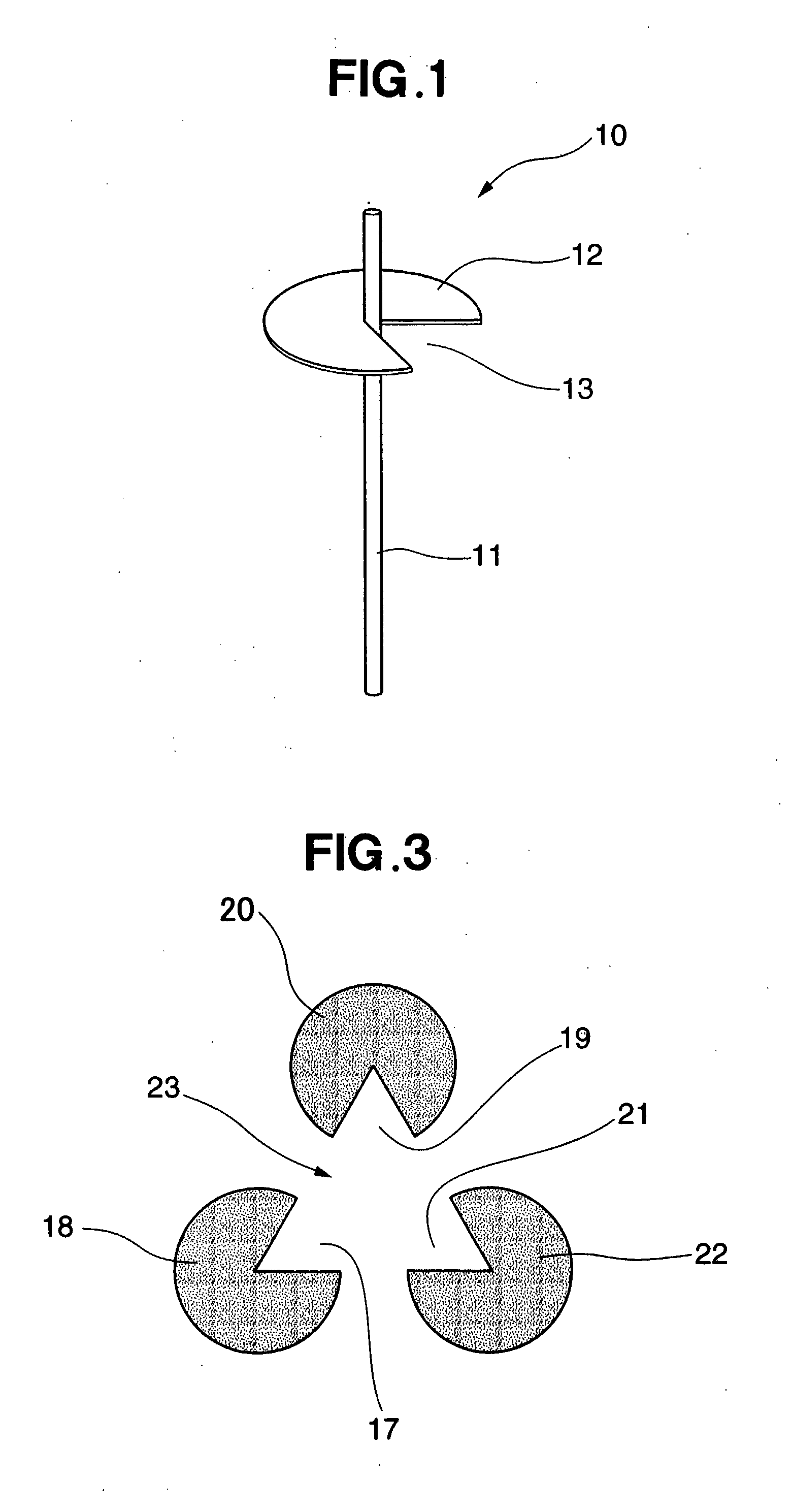
[0021]FIG. 1 is a perspective view explanatory of a corner pole 10 that constitutes a principal part of a visual recognition assistance device for a vehicle according to an embodiment of the present invention.

[0022] As shown in FIG. 1, the corner pole 10 includes a pole section 11 and a plate section 12. The pole section 11 comprises a plurality of telescopically-connected rods of different diameters, and the plate section 12 is in the form of a thin circular plate (disk) with a substantially-sectorial recessed portion 13 formed therein.

[0023] In the instant embodiment, the pole section 11 is formed of metal similarly to the conventional corner poles, while the plate section 12 is formed of plastic to reduce its weight. However, the plate section 12 may be formed of any other suitable material than plastic, such as metal. The pole section 11 in its telescopically-expanded position has a length equal to or greater than the conventional corner poles. In view of the overall size of t...


PUM


Abstract

Visual recognition assistance device (10) for a vehicle includes a pole section (11) provided at a corner area of the vehicle, and a plate section (12) provided at an intermediate portion or end portion of the pole section in substantially parallel relation to the ground surface. The plate section is in any one of disk, rectangular, triangular, kite and bar shapes. The plate section includes a pole-section position indicating portion (13) to point to the pole section in a highlighted fashion. The pole-section-position indicating portion may be in the form of a recessed portion, colored portion, light emitting portion, projecting portion or bar.

Description

TECHNICAL FIELD [0001] The present invention relates generally to visual recognition assistance devices for vehicles, and more particularly to an improved visual recognition assistance device which permits improved positional recognition of a fore end portion of a motor vehicle (i.e., which can enhance the so-called “bonnet end visibility” or “body end visibility” of the vehicle). BACKGROUND ART [0002] Many of the today's motor vehicles are constructed to assume a low bonnet height in order to improve design features and aerodynamic characteristics of the vehicles. In such motor cars, the fore end of the vehicle i.e., fore end of the bonnet) can hardly been seen, or can not be seen at all, from the driver's seat; on narrow streets and parking lots, however, there arises a need for the vehicle driver to accurately recognize a fore end position of the vehicle. Heretofore, corner poles have been known as visual recognition assistance device for allowing a human vehicle driver to easily...

Claims


Application Information

Patent Timeline
Patent Type & Authority Applications(United States)
IPC IPC(8): B60Q1/28
CPCB60Q1/484B60R11/00B62D15/027B60R2011/0005B60R19/48
Inventor MATSUMOTO, YOSHIYUKIMARUYAMA, KAZUYUKI
Owner HONDA MOTOR CO LTD
Learn More