
Secondary lock for a downhole tool

a secondary lock and downhole tool technology, applied in the direction of sealing/packing, fluid removal, borehole/well accessories, etc., can solve the problems of loose seals, downhole tools are particularly prone to leakage, downhole tools may leak at high pressure, etc., to reduce the leakage of seals and increase the pack-off force of downhole tools.

Active Publication Date: 2007-10-04
SMITH INT INC
View PDF26 Cites 100 Cited by
  • Summary
  • Abstract
  • Description
  • Claims
  • Application Information

AI Technical Summary

Benefits of technology

The present invention is related to a downhole tool used in oil and gas drilling operations. The tool includes a mandrel, a sealing element, a lock ring, and a cone. The tool is designed to increase the pack-off force, which is the force that seals the tool from leaks. The method involves setting the tool and applying a differential pressure to the sealing element. The invention also includes a secondary lock that connects the mandrel and the lock ring, which helps to further improve the sealing performance of the tool. The secondary lock includes an arm and a threaded portion that is engaged with the upper cone of the tool. The technical effects of the invention include improved sealing performance, reduced leakage, and better well control during drilling operations.

Problems solved by technology

It has been found that downhole tools may leak at high pressures unless they include a means for increasing the seal energization, such as a pressure responsive self-energizing feature.
This may cause a loosening of the seal.
Downhole tools are also particularly prone to leak if fluid pressures on the packers are cycled from one direction to the other.
The Allen seal elements are actuated in such a way that the movable sleeves / pistons which effect the increased energization engage the seal elements across only a part of their diameters and may cause extrusion of the elastomeric members around them at the upper and lower extremities of the stack of seal elements.
Such extrusion around the sleeves and pistons may cause uneven stresses in or even damage to the seal elements, and could lead to seal failure.
Accordingly, in the event of pressure cycling, the sleeve may become stuck or may be prevented from moving fully or properly in one direction or the other to energize the seal.

Method used


Image

  • Secondary lock for a downhole tool
  • Secondary lock for a downhole tool
  • Secondary lock for a downhole tool

Examples


Embodiment Construction

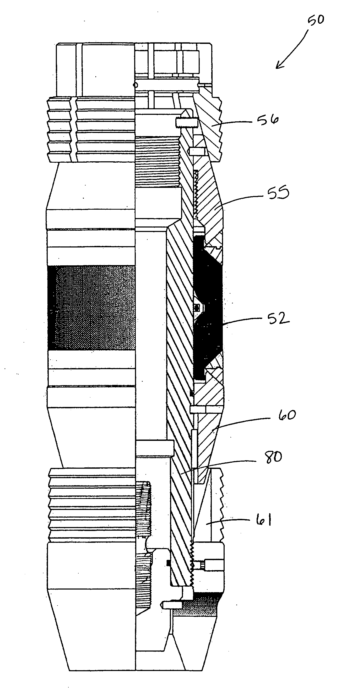
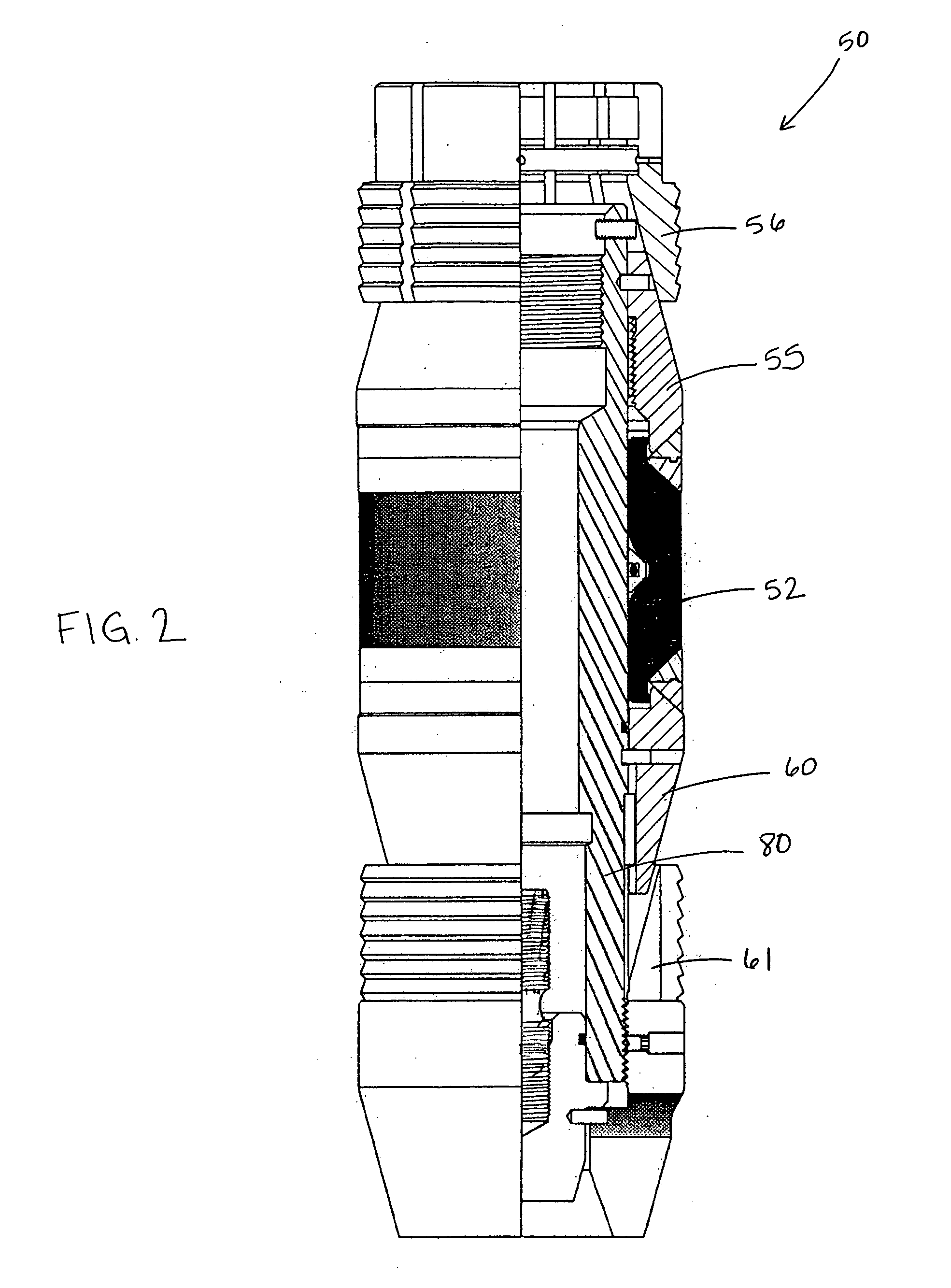
[0031] In one aspect, embodiments of the invention relate to a downhole tool for sealing tubing or other pipe in a casing of a well. In particular, disclosed embodiments disclose a downhole tool, for example, a bridge plug or a packer, having a secondary lock to prevent leakage of fluids around the set downhole tool. Leakage often occurs when high pressure, that is pressure greater than the setting force, is applied to the downhole tool. Embodiments of the present invention may provide a more efficient and leak-resistant downhole tool for sealing tubing or pipe. Additionally, embodiments of the present invention may reduce loosening of the seal formed between the downhole tool and the tubing or pipe. Further, embodiments of the present invention may provide a method of further energizing a sealing element of a downhole tool after the downhole tool is set. Further still, embodiments of the present invention may provide a method of retrofitting a typical downhole tool with a secondary...


PUM


Abstract

A downhole tool includes a mandrel, a sealing element disposed around the mandrel, an upper cone disposed above the sealing element and a lower cone disposed below the sealing element, an upper slip assembly disposed above the upper cone and a lower slip assembly disposed below the sealing element, at least one lock ring configured to maintain energization of the sealing element when the downhole tool is set, and a secondary lock that couple the upper cone with the at least one lock ring. A method of increasing pack-off force of a downhole tool includes setting the downhole tool and energizing further the sealing element by applying a differential pressure to the downhole tool. A method of retrofitting a downhole tool includes providing a secondary lock disposed around a mandrel, the secondary lock including at least one arm having an axial portion extending downwardly therefrom and a threaded portion, and assembling the secondary lock to the downhole tool, the assembling including engaging the threaded portion of the secondary lock to a threaded surface of an upper cone disposed around the mandrel of the downhole tool.

Description

BACKGROUND OF INVENTION [0001] 1. Field of the Invention [0002] The invention relates generally to methods and apparatus for drilling and completing well bores. More specifically, the invention relates to methods and apparatus for an secondary lock for a downhole tool. [0003] 2. Background Art [0004] In the drilling, completing, or reworking of oil wells, a great variety of downhole tools are used. For example, but not by way of limitation, it is often desirable to seal tubing or other pipe in the casing of a well, such as when it is desired to pump cement or other slurry down the tubing and force the cement or slurry around the annulus of the tubing or out into a formation. In some instances, perforations in the well in one section need to be isolated from perforations in a second section of the well. Typically, the wellbore is lined with tubular or casing to strengthen the sides of the borehole and isolate the interior of the casing from the earthen walls therearound. In order to ...

Claims


Application Information

Patent Timeline
Patent Type & Authority Applications(United States)
IPC IPC(8): E21B33/12
CPCE21B23/06E21B33/134E21B33/1295E21B33/129E21B33/12E21B33/1293E21B33/1208E21B33/128
Inventor ROBERTS, WILLIAM M.MELENYZER, GEORGE J.
Owner SMITH INT INC
Features
  • Generate Ideas
  • Intellectual Property
  • Life Sciences
  • Materials
  • Tech Scout
  • Unparalleled Data Quality
  • Higher Quality Content
  • 60% Fewer Hallucinations
Learn More