
Shelving system for use with load cell

Inactive Publication Date: 2007-10-04
INVENTROL
View PDF12 Cites 9 Cited by
  • Summary
  • Abstract
  • Description
  • Claims
  • Application Information

AI Technical Summary

Benefits of technology

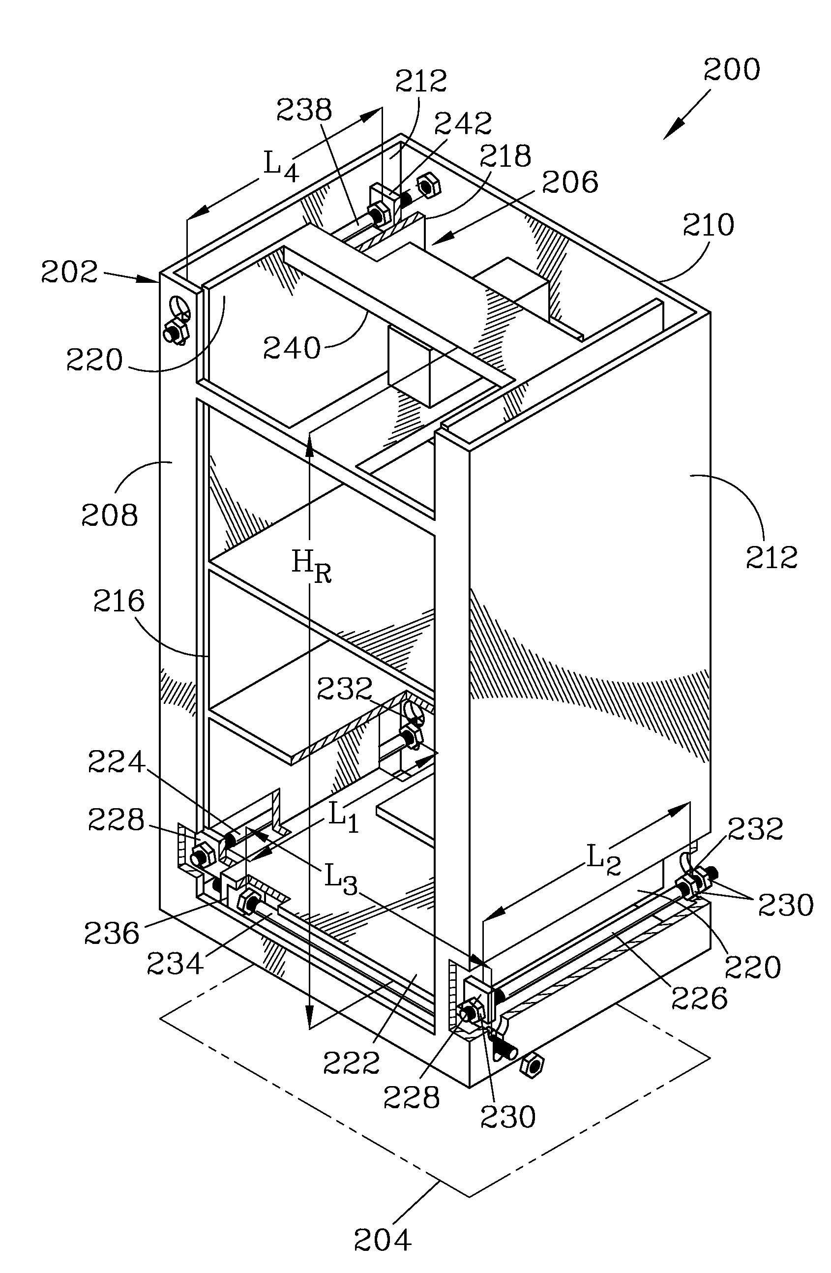
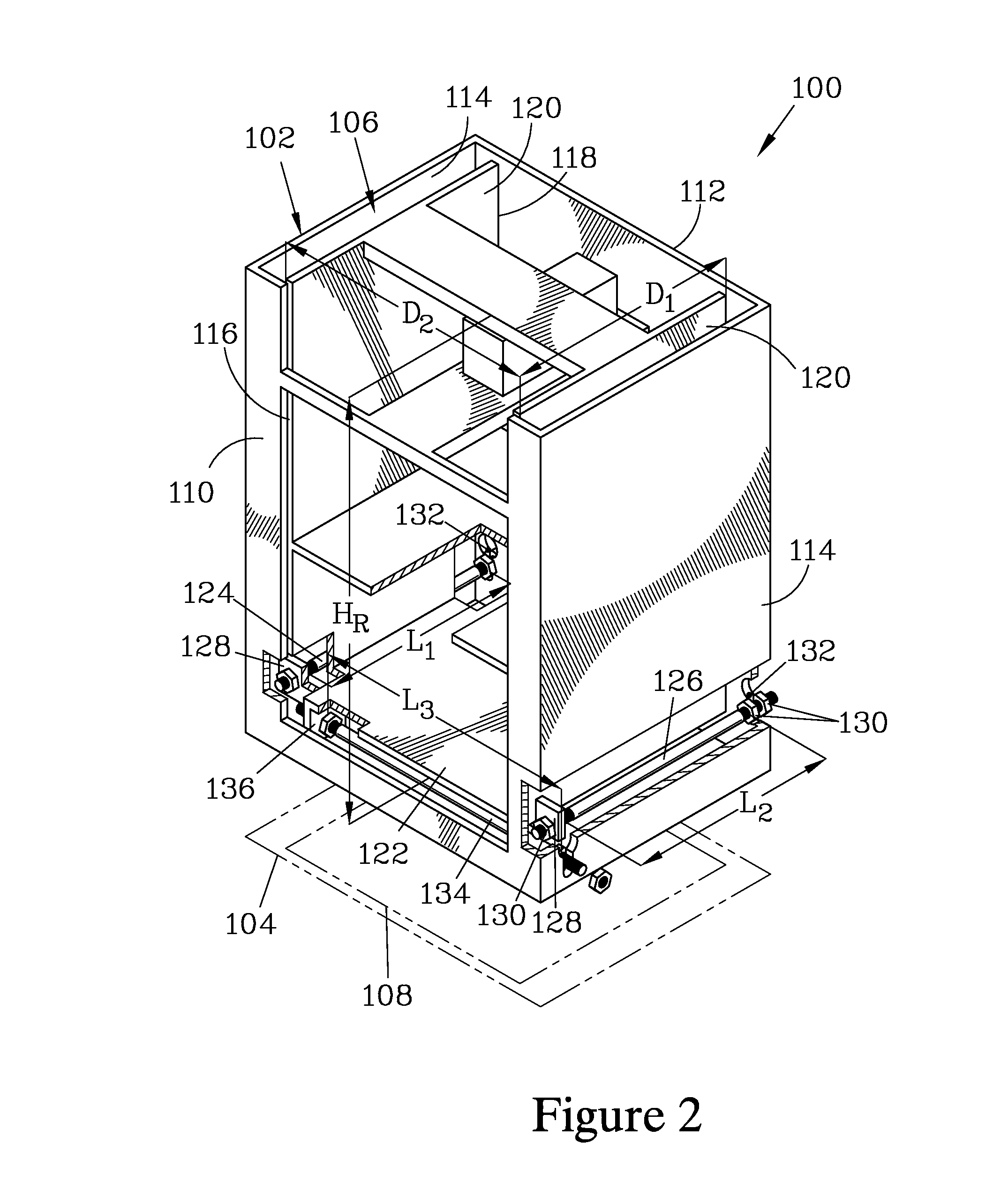
[0008]To provide a response to changes in load which is rapid and reliable, it is important to stabilize the rack in the event that the user disturbs the stability of the rack by loading or removing stock from the rack; such loading and unloading may introduce transient motions which, without structure to damp the effect of such disturbances, will require substantial time to decay. The stiffness of the rack will, in part, limit the transient motions resulting from twisting and bending of the rack that may occur when the rack is loaded. To further stabilize the rack, it is necessary to limit the transient motion between the rack and the frame but, at the same time, the stabilizing structure employed should not cause resistive forces that will impede rapid response to small load changes. To provide such stabilization, an anti-sway and transient damping system is provided (hereinafter referred to as an anti-sway system).
[0016]The lever arms are preferably made from rod stock, typically round, square or rectangular in shape. The cross section should be sufficiently robust that the arms will not be subject to plastic deformation in use. Cylindrical rods have a benefit in that they can be easily threaded for attaching to the frame and to the rack, and their effectiveness is not dependent on the angular orientation of the rod when installed, as would be the case for square or rectangular rods.

Problems solved by technology

This is particularly true for an inventory of items in a retail setting, where the frequent loading or removal of items causes torques on the supporting element due to friction, impacts, and changes in the distribution of weight.
This apparatus would not be suitable for storing and monitoring an inventory of individual product items, and the stabilizers do not appear to be designed to counter forces applied at a large vertical distance from the stabilizers.
This apparatus is reported to be designed to monitor heavy loads, and thus the massive structure of the connection, the rigid connections between the arms to resist torsional loads, and frictional resistance to pivoting may not affect its performance in this role; however, this apparatus would not be well suited to measuring small weight changes associated with shelved inventory.

Method used


Image

  • Shelving system for use with load cell
  • Shelving system for use with load cell
  • Shelving system for use with load cell

Examples


Embodiment Construction

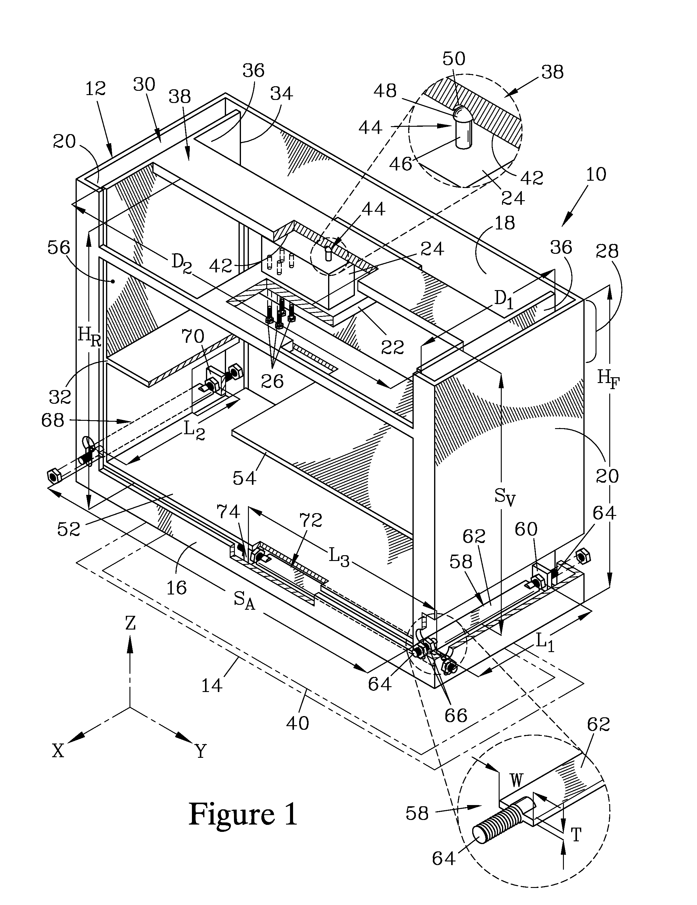
[0027]FIG. 1 is an isometric view of a shelving system 10 that forms one embodiment of the present invention. The shelving system 10 has a frame 12 having a frame height HF and a rectangular frame footprint 14. The frame 12 is bounded by a frame front face 16 and a frame rear face 18, which form a first pair of frame faces, and by a pair of frame side faces 20, which form a second pair of frame faces. The frame 12 has a load cell support platform 22 for supporting a load cell 24. The load cell 24 is attached to the support platform 22 by bolts 26 and resides in a top region 28 of the frame 12.

[0028]A rack 30 is provided, having a rack height HR. The rack 30 is bounded by a rack front face 32 and a rack rear face 34, which form a first pair of rack faces that are separated by a first rack face pair separation distance D1. The rack 30 is further bounded by a pair of rack side faces 36 which form a second pair of rack faces that are separated by a second rack face pair separation dista...


PUM


Abstract

A shelving system for use with a load cell has a frame, to which the load cell is mounted, and a rack residing within the frame and having a load cell proximity surface supported on the load cell by a pivotal contact element. The rack is stabilized by an anti-sway system having three lever arms connected between the frame and the rack and spaced apart from the load cell proximity surface. A first and a second lever arm are parallel and spaced apart from each other, and extend parallel to two faces of the rack, while a third lever arm extends substantially normal to the first and the second lever arms. A fourth lever arm can be provided, located in close proximity to the load cell proximity surface and extending parallel to at least one of the other lever arms.

Description

FIELD OF THE INVENTION[0001]The present invention relates to a shelving system for use with a load cell to allow the weight of inventory items stored on the shelving system to be monitored.BACKGROUND OF THE INVENTION[0002]It is frequently desirable to monitor an inventory to reduce pilferage. One means for doing so is by measuring the change, as a function of time, of the weight of a support structure on which the inventory is stored. The change in weight is monitored by one or more scales on which the support structure rests. U.S. Publication No. 2005 / 0077352A1 teaches one example of an inventory monitoring system which uses weight changes to monitor inventory. To avoid erroneous readings due to artifacts resulting from loading and unloading inventory from the support structure, it is desirable to configure the support system to limit the motion of the supporting structure to essentially vertical motion, and to rapidly damp any transitory motion associated with horizontal motion. T...

Claims


Application Information

Patent Timeline
IPC IPC(8): G01G21/12G01G21/24G01G23/06
CPCG01G19/415G01G19/4144
Inventor GUDBJARTSSON, LARUS H.INGOLFSSON, HALFDAN
Owner INVENTROL
Learn More