System and method for fusing an image

a technology of system and method, applied in the field of system and method for fusing an image, can solve the problems of not seeing a person, typically not having sufficient resolution and sensitivity to provide acceptable imagery of a scen

Inactive Publication Date: 2007-10-04
L 3 COMM INSIGHT TECH
View PDF25 Cites 58 Cited by
  • Summary
  • Abstract
  • Description
  • Claims
  • Application Information

AI Technical Summary

Problems solved by technology

A drawback to image intensification night vision systems is that they may be attenuated by smoke and heavy sand storms and may not see a person hidden under camouflage.
One advantage of infrared sensors is that they are less attenuated by smoke and dust and a drawback is that they typically do not have sufficient resolution and sensitivity to provide acceptable imagery of a scene.

Method used


Image

  • System and method for fusing an image
  • System and method for fusing an image
  • System and method for fusing an image

Examples


Embodiment Construction

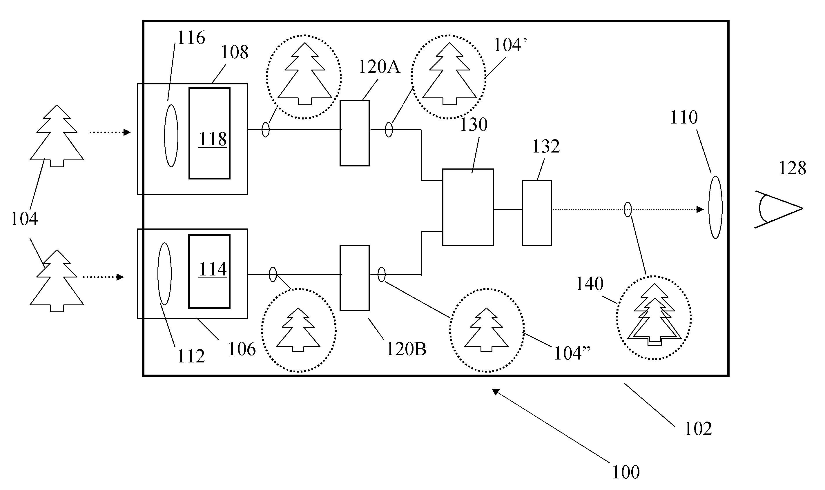
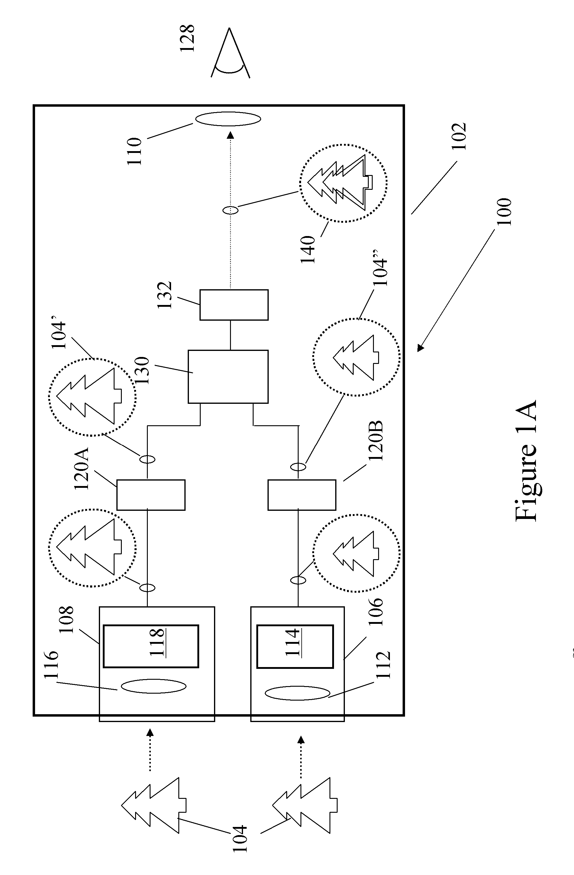
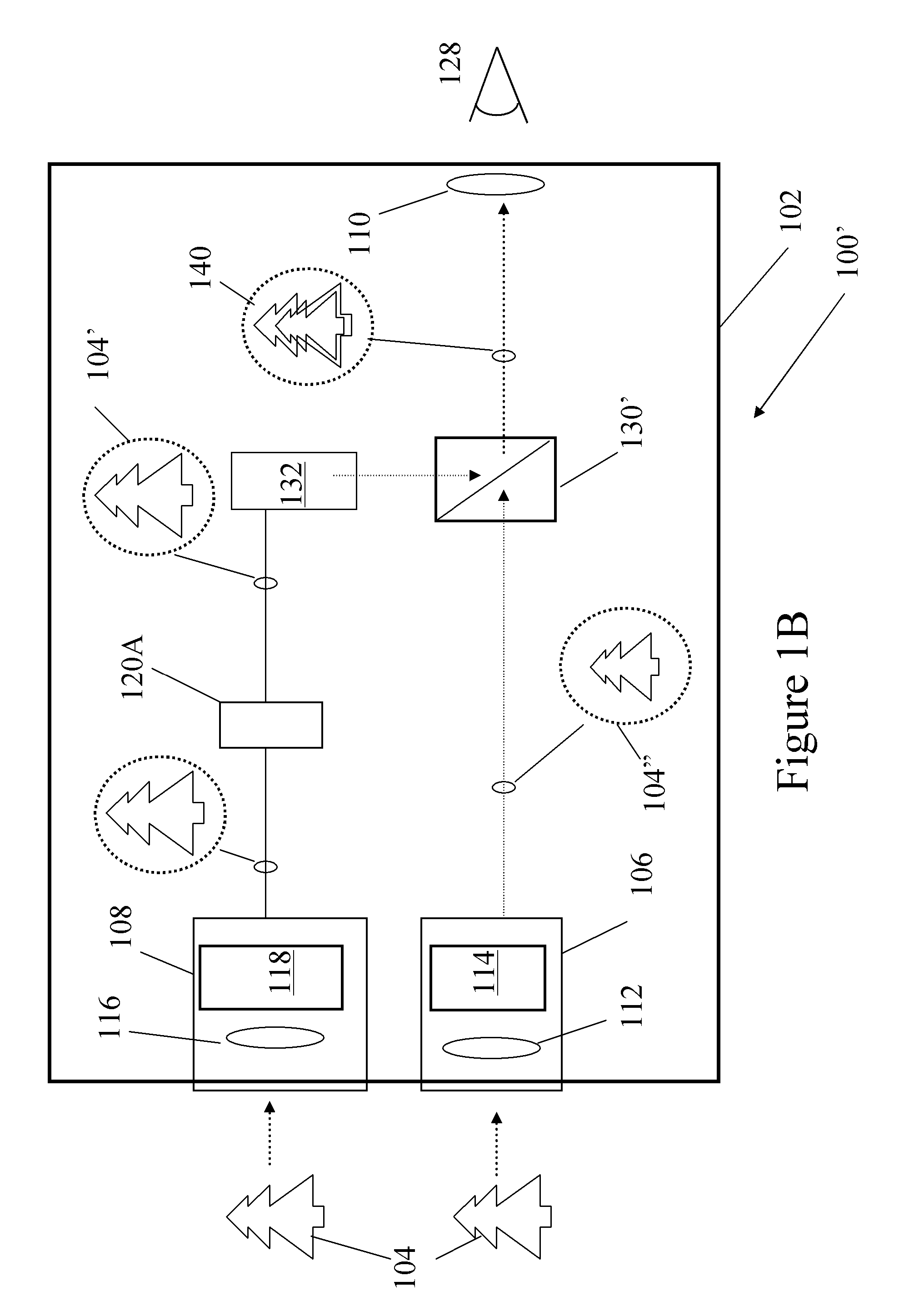
[0017]FIG. 2A is a block diagram of a first fusion vision system 200 and FIG. 2B is a block diagram of a second fusion vision system 200′, consistent with the present invention. The electronics and optics may be housed in a housing 202. Information from a first channel (I2) channel 206 and a second channel 208 may be fused together in an image combiner 230, 230′ for viewing by an operator 128. A channel may be an path through which scene information may travel. Depending on the type of sensors in the I2 channel 206 and the thermal channel 208, and the type of image combiner 230, 230′ utilized, the output of the I2 channel 206 may or may not be processed in a processor 220B and the output of the thermal channel 208 may or not be processed in a processor 220A. The first channel 206 may be configured to process information in a first range of wavelengths (the visible portion of the electromagnetic spectrum from approximately 400 nm to approximately 900 nm) and the second channel 208 ma...


PUM


Abstract

A fusion vision system has a first sensor configured to detect scene information in a first range of wavelengths, a second sensor configured to detect scene information in a second range of wavelengths, and a processor configured to resize one of a first and a second image to improve viewability of the fused scene.

Description

CROSS REFERENCE TO RELATED APPLICATIONS[0001]The present application claims the benefit of copending U.S. patent application Ser. No. 11 / 173,234, filed Jul. 1, 2005 and U.S. Provisional Patent Application Ser. No. 60 / 728,710, filed Oct. 20, 2005, the entire disclosures of which are incorporated herein by reference.BACKGROUND OF THE INVENTION[0002]Night vision systems include image intensification, thermal imaging, and fusion monoculars, binoculars, and goggles, whether hand-held, weapon mounted, or helmet mounted. Image intensification night vision systems are typically equipped with one or more image intensifier tubes to allow an operator to see visible wavelengths of radiation (approximately 400 nm to approximately 900 nm). They work by collecting the tiny amounts of light, including the lower portion of the infrared light spectrum, that are present but may be imperceptible to our eyes, and amplifying it to the point that an operator can easily observe the image through an eyepiec...

Claims


Application Information

Patent Timeline
Patent Type & Authority Applications(United States)
IPC IPC(8): H01J43/00
CPCH01J31/50H01J2231/50063H04N5/2258H04N5/3572H04N5/23293H04N5/33H04N5/332H04N5/23232H04N23/45H04N23/951H04N23/63H04N23/11H04N25/61
Inventor HOHENBERGER, ROGER T.
Owner L 3 COMM INSIGHT TECH
Why Eureka
Try Eureka