Object-detecting lighting system and method

a technology of object detection and lighting system, applied in the field of object detection, can solve problems such as insufficient power output in a single uni

Active Publication Date: 2007-10-04
LEDDARTECH INC
View PDF9 Cites 121 Cited by
  • Summary
  • Abstract
  • Description
  • Claims
  • Application Information

AI Technical Summary

Benefits of technology

[0005] It is an object of the present invention to provide a novel object-detecting lighting system.

Problems solved by technology

However, until recently these LEDs were not showing sufficient power output in a single unit to provide ambient lighting or to be part of lamps and luminaires.

Method used


Image

  • Object-detecting lighting system and method
  • Object-detecting lighting system and method
  • Object-detecting lighting system and method

Examples


Embodiment Construction

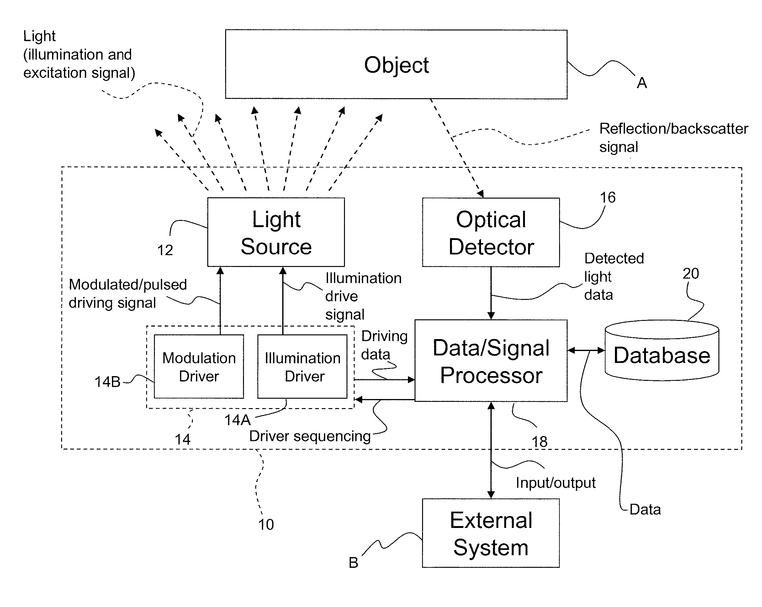
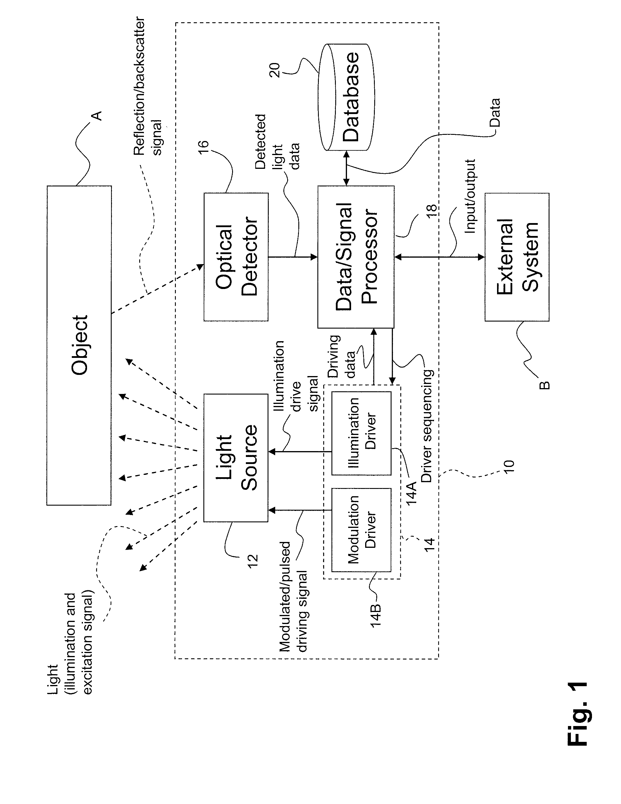
[0018] Referring to FIG. 1, an object-detecting lighting system in accordance with a preferred embodiment of the present invention is generally shown at 10.

[0019] The system 10 has a visible-light source 12. The visible-light source 12 has a first function the emission of visible light with enough intensity such that a user can collect information from its environment in a direct way (by seeing the light source 12) or indirect way (from scene illumination) through human vision, whether it be by illumination of the environment or emission of a signal. Examples of such lighting systems include lamps, illuminators, signs and displays, status indicators, amongst others. In a preferred embodiment, the visible-light source 12 has one or more LEDs, in accordance with the selected application of the system 10, a few of which are described hereinafter. As examples, the visible-light source 12 may be in the form of a home lighting fixture (e.g., lamp, illuminators), a traffic light, a street...


PUM


Abstract

An object-detecting lighting system comprises a light source emitting visible light. A source controller is connected to the light source to drive the light source into emitting the visible light in a predetermined mode. An optical detector is positioned with respect to the light source and is adapted to detect the visible light as reflected/backscattered by an object. A data/signal processor is connected to the source controller and the optical detector to receive detection data from the optical detector. The data/signal processor produces a data output associated to the object as a function of the predetermined mode and the detection data.

Description

CROSS-REFERENCE TO RELATED APPLICATION [0001] This patent application claims priority on U.S. Provisional Patent Application No. 60 / 751,284, filed on Dec. 19, 2005.FIELD OF THE INVENTION [0002] The present invention generally relates to lighting systems and more particularly to object-detection using visible light emitted by a lighting system. BACKGROUND OF THE INVENTION [0003] It has been known since the 1990's that white light-emitting diodes (hereinafter “LEDs”) can provide light that in some ways reproduces incandescent or fluorescent lighting systems with higher efficiency. These LEDs also emit light almost instantaneously (very fast turn on) and also stop emitting light almost instantaneously as well (very fast shut down response). However, until recently these LEDs were not showing sufficient power output in a single unit to provide ambient lighting or to be part of lamps and luminaires. For a few years, LEDs have been a part of flashlights or small lighting devices that can ...

Claims


Application Information

Patent Timeline
Patent Type & Authority Applications(United States)
IPC IPC(8): G06M7/00G01S17/931
CPCB60W40/04G01P13/00G01S7/481G01S7/4814G08G1/095G01S17/42G01S17/936G08G1/04G01S17/06G01S17/931
Inventor CANTIN, DANIELMIMEAULT, YVANGALLANT, PASCAL
Owner LEDDARTECH INC
Why Eureka
Try Eureka