Meander feed structure antenna systems and methods

Active Publication Date: 2007-10-04
HONG KONG APPLIED SCI & TECH RES INST
View PDF14 Cites 7 Cited by
  • Summary
  • Abstract
  • Description
  • Claims
  • Application Information

AI Technical Summary

Benefits of technology

[0007] In this example, the at least partial canceling of the current in the first current path may allow the resonant frequency of the first current path to be tuned effectively independently from the resonant frequency of the second current path. Further, the radiating portion of the meander feed may be used by the antenna system to add a resonant frequency to its spectrum of operating bands or it may be tuned to match the reson

Problems solved by technology

In other cases, especially when a PCB includes materials that readily absorb Radio Frequency (RF) energy and turn it into heat, such coupling can further lower t

Method used


Image

  • Meander feed structure antenna systems and methods
  • Meander feed structure antenna systems and methods
  • Meander feed structure antenna systems and methods

Examples


Embodiment Construction

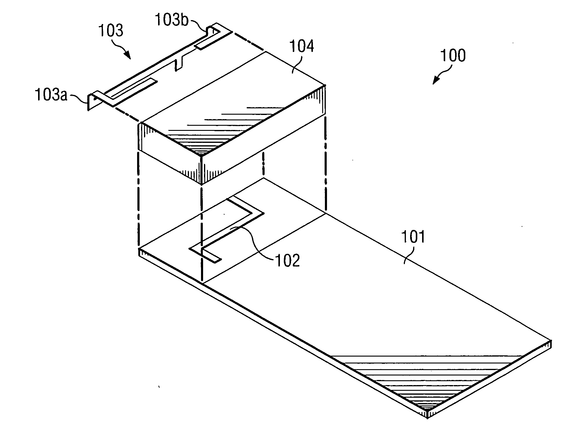
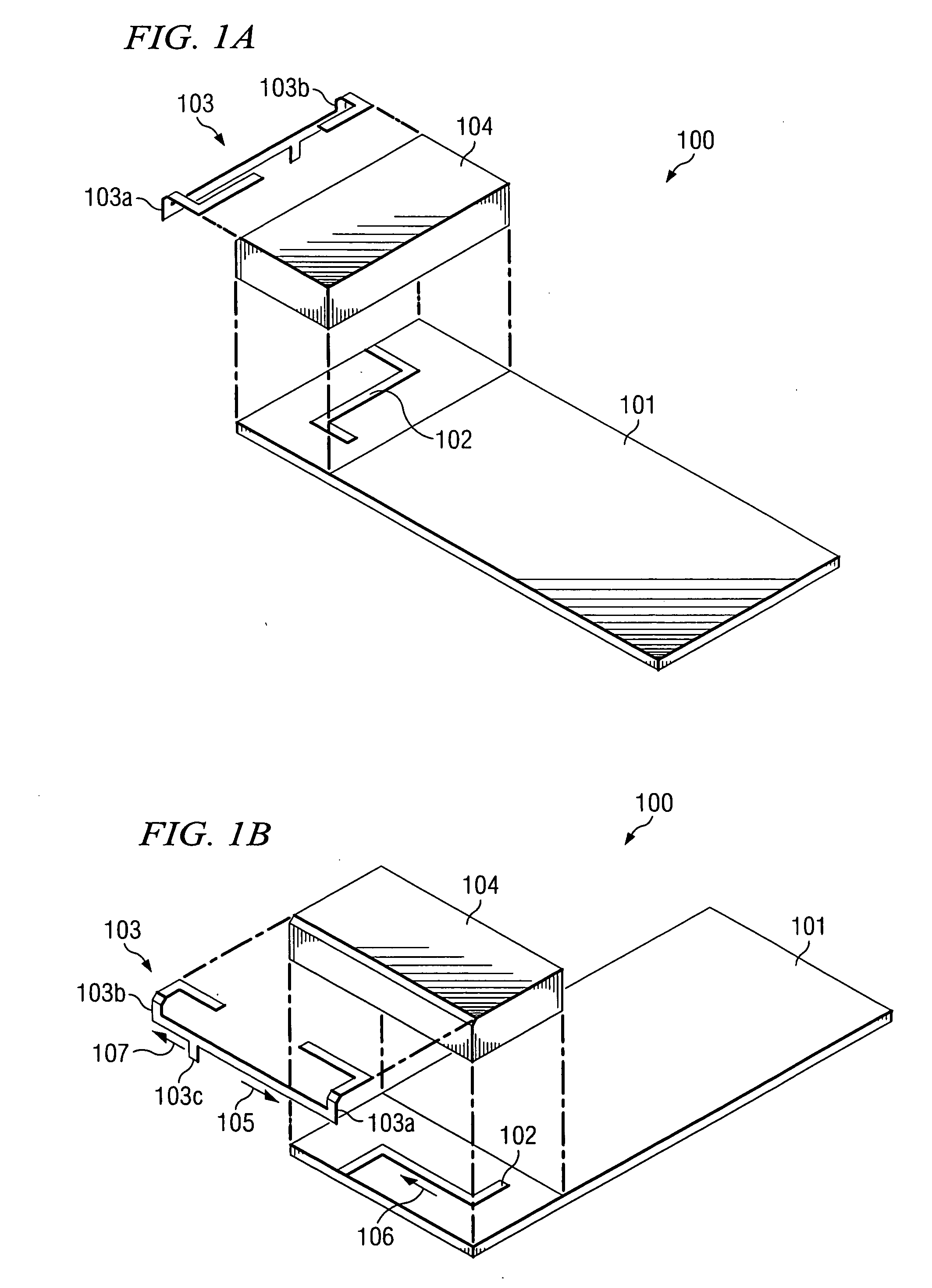
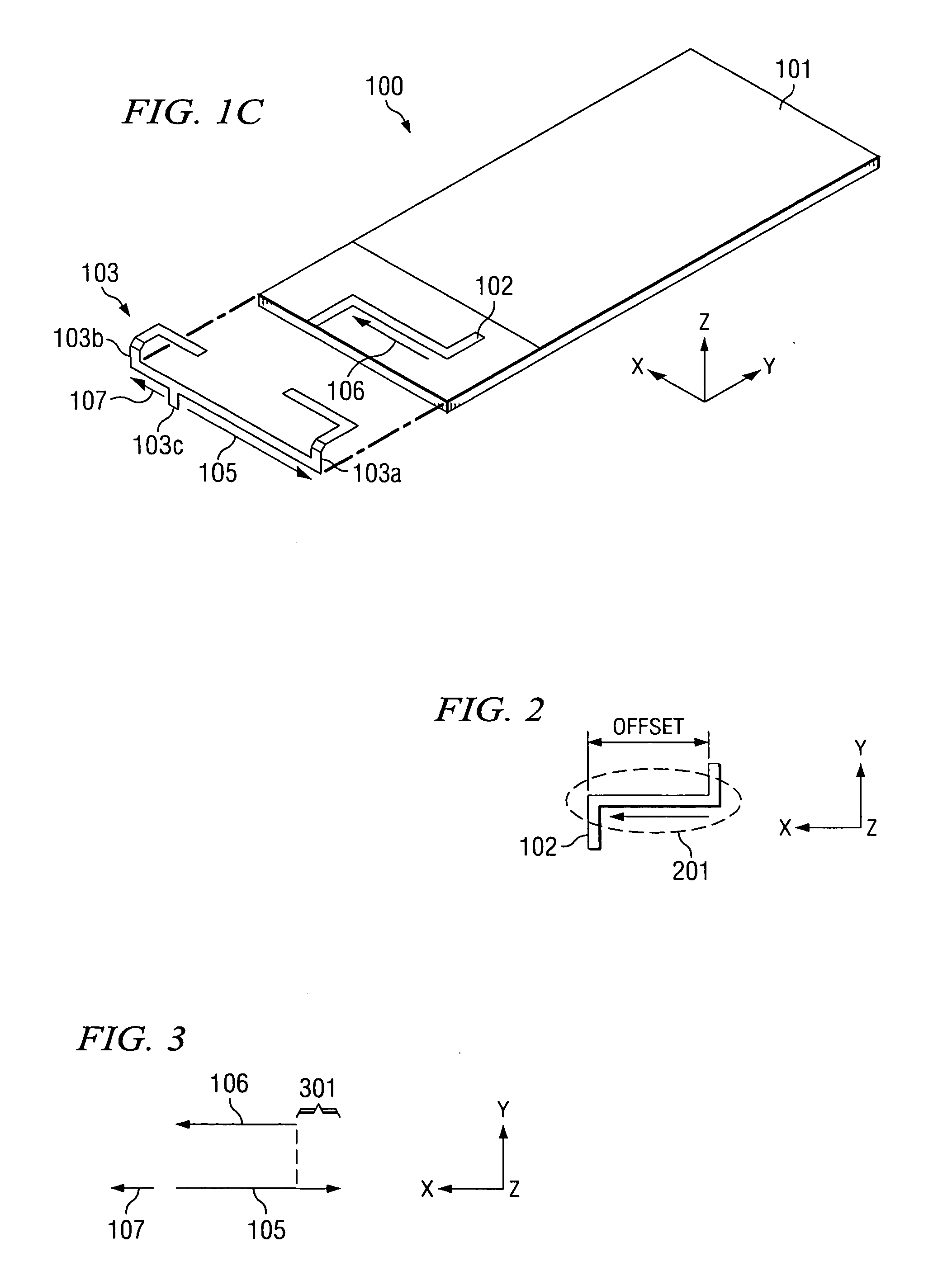
[0018]FIGS. 1A-1C are exploded views of exemplary antenna system 100 adapted according to one embodiment of the present invention. Antenna system 100 includes meander feed structure 102. Meander feed structure 102 provides a conducting path from one feed point to another feed point, such as in system 100, a feed point from Printed Circuit Board (PCB) 101 to feed point 103c of antenna element 103. Meander feed structure 102 allows a placement of feed point 103c to be at least somewhat independent of a placement of the feed point on PCB 101. Also, as explained further below, the placement of meander feed structure 102 affects the resonant frequencies of antenna system 100 and the coupling between the currents responsible for those resonant frequencies.

[0019] Antenna system 100 also includes antenna element 103, which is connected to meander feed structure 102 by feed point 103c. In this example, antenna element 103 is a “U-shaped” element that is three-dimensional and ungrounded. In ...


PUM


Abstract

A transmitting and receiving system including an antenna element having first and second current paths, and a meander feed line connected to said first and second current paths, the meander feed line including a radiating portion parallel to the first current path, wherein a current in the radiating portion is in a direction opposite of a current in the first current path, and wherein a current in the second current path is in a direction the same as the current in said radiating portion.

Description

TECHNICAL FIELD [0001] Various embodiments of the present invention relate in general to antenna systems and methods of operation thereof, and more specifically to multi-band antenna systems with meander feed structures and methods of operation thereof. BACKGROUND OF THE INVENTION [0002] Many wireless devices include antennas that are printed or mounted on Printed Circuit Boards (PCBs) with other circuits. During operation, currents in an antenna may couple with currents in wires on the PCB. Coupling is a phenomenon that is known to designers of electromagnetic devices, and it involves both capacitive and inductive effects and includes the transfer of electromagnetic energy between one current and the other current. [0003] Coupling is illustrated in FIGS. 8A-C. The greatest amount of coupling occurs with parallel currents, as in FIGS. 8A and 8C. If the currents are in opposite directions, the current generally cancel, at least partially, if the spacing between the conductors is with...

Claims


Application Information

Patent Timeline
IPC IPC(8): H01Q1/24H01Q5/15
CPCH01Q1/243H01Q1/36H01Q5/371H01Q5/00H01Q1/38
Inventor ROWELL, CORBETT
Owner HONG KONG APPLIED SCI & TECH RES INST
Why Eureka
Try Eureka