
Draggable maps

a map and pixel technology, applied in the field of digital map generation, can solve the problems of difficult to render a map centered on a specific requested location, and it is impossible for an application to request a tile of a different siz

Active Publication Date: 2007-10-04
UBER TECH INC
View PDF5 Cites 49 Cited by
  • Summary
  • Abstract
  • Description
  • Claims
  • Application Information

AI Technical Summary

Benefits of technology

[0012] Because map tiles are rendered dynamically, they can be centered at essentially arbitrary locations. Further, the appearance of each tile can be changed by using parameters in the resource identifier request from the client to the server—for example, to change colors on the map. Overlay data such as route guidance can be rendered as part of the tile, since the tile is rendered dynamically, when requested by the client. Zooming is also simplified compared to conventional methods, and can be achieved by providing the server with a zoom factor along with a number of tiles the image has been panned from the original centered location.

Problems solved by technology

One drawback to the conventional approach to map rendering is that if a client is attempting to determine the boundaries of tiles in their spatial positions, the client has to know the projection that is being used to draw the map.
In addition, because conventional applications use pre-rendered maps, they have certain drawbacks.
Because the center of a tile grid is predetermined, it is difficult to render a map centered on a specific requested location such as a street address, without performing some additional steps to slide the grid to the desired location.
In addition, tile sizes are predefined, making it impossible for an application to request a tile of a different size, unless such a tile has been pre-rendered.

Method used


Image

  • Draggable maps
  • Draggable maps
  • Draggable maps

Examples


Embodiment Construction

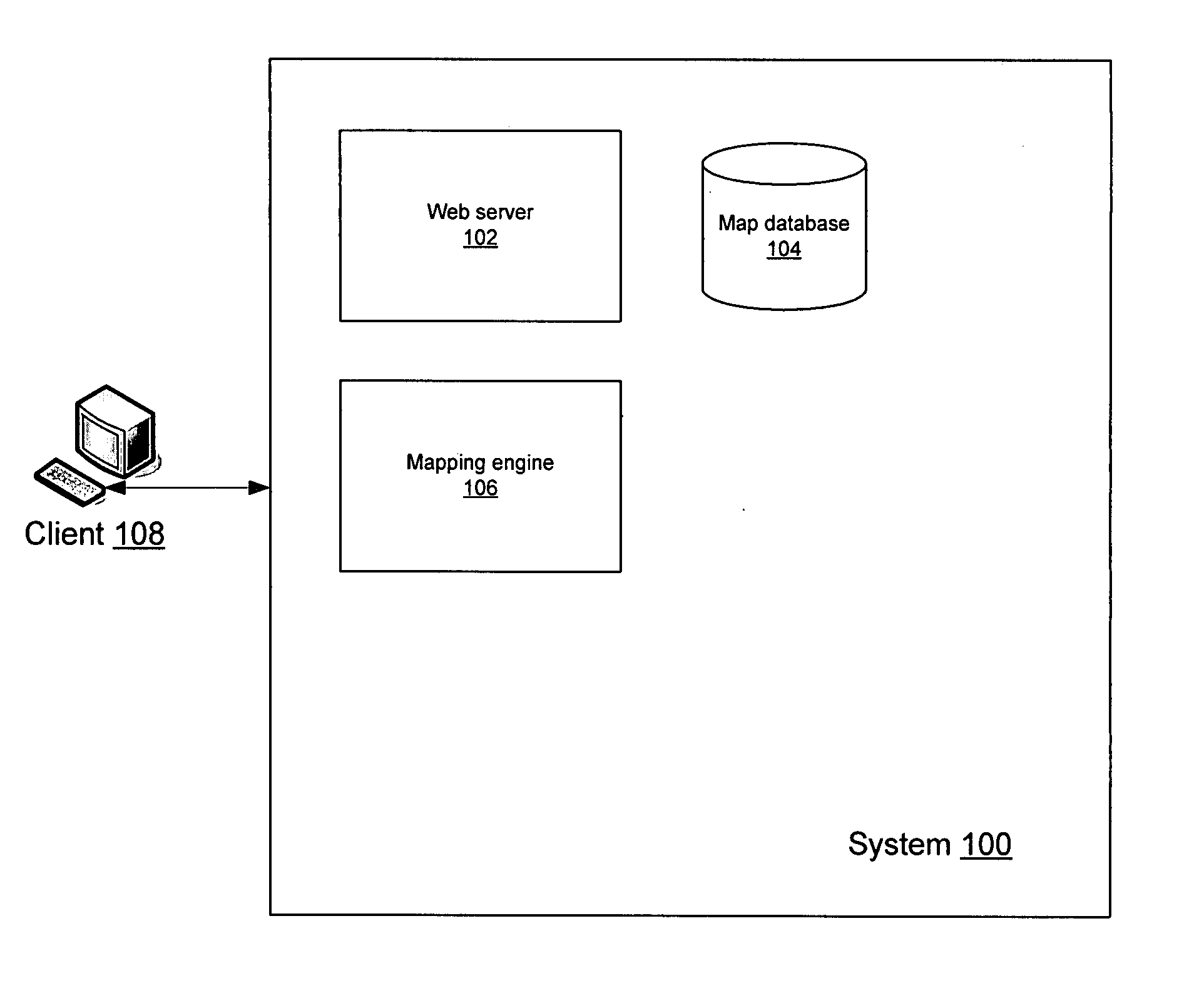
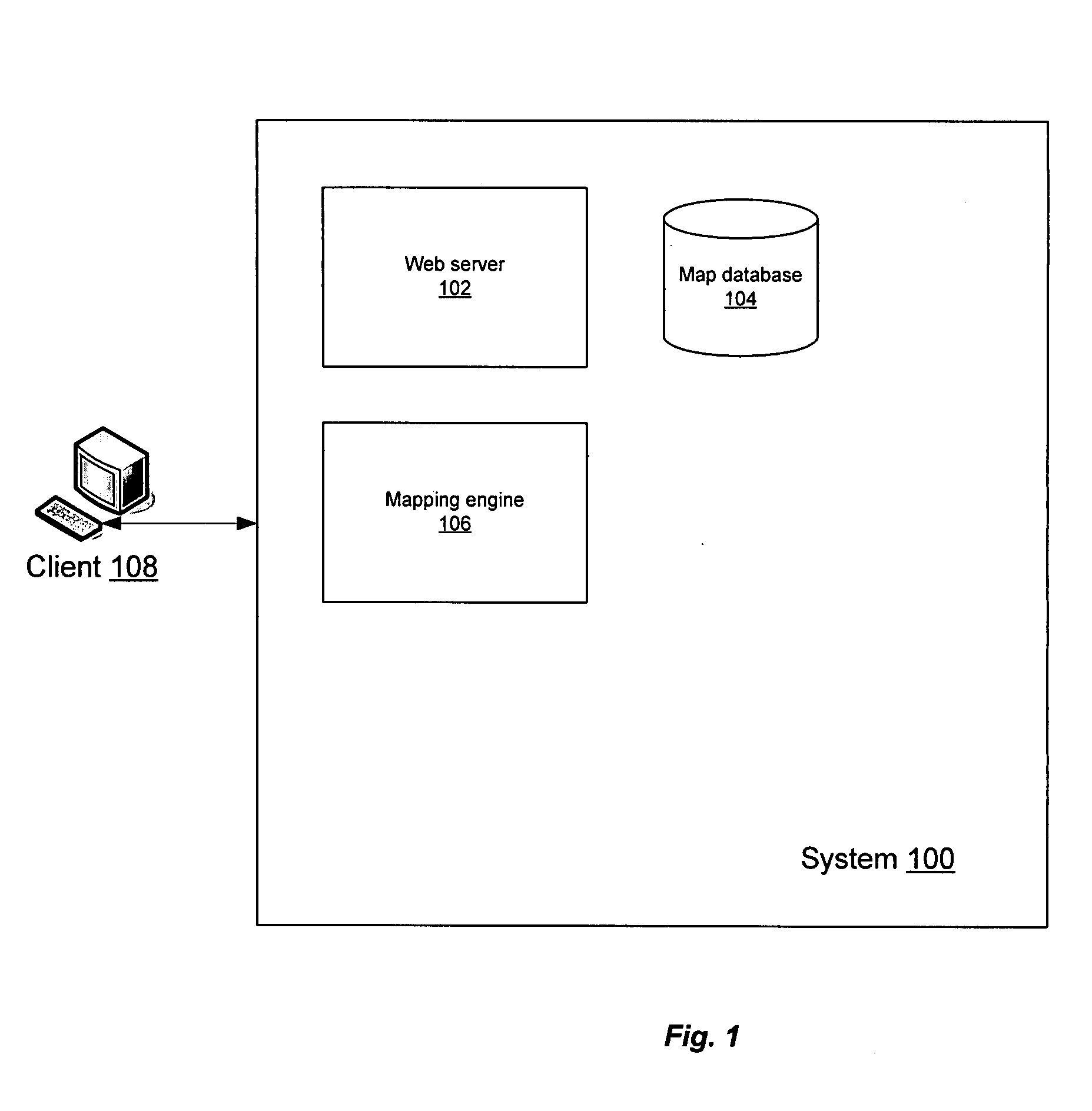
[0023]FIG. 1 illustrates a system for providing dynamically-rendered maps in accordance with an embodiment of the present invention. System 100 includes a map database 104, a mapping engine 106 and a web server 102. Also shown is a client 108.

[0024] Map database 104 contains digitized map data used by mapping engine 106 for routing, geocoding, map rendering and other geospatial functions. Mapping engine 106 receives and responds to requests from web server 102 for map data, including dynamically-rendered tiles. Web server 102 includes a conventional web server application such as the Apache HTTP Server by the Apache Software Foundation or the Internet Information Services web server by Microsoft. In addition, web server 102 includes logic for receiving requests for dynamic maps from client 108, communicating the requests to mapping engine 106, receiving the dynamic map data and providing the map data to client 108.

[0025] Also shown in FIG. 1 is client 108. Client 108 in one embodi...


PUM


Abstract

A web server receives a request from a client specifying a location and a bounding area. A mapping engine creates a tile grid centered at the specified location. A seed tile is created, including or adjacent to the center location. The web server creates a resource identifier for each tile in the tile grid, and returns the tile grid including the resource identifiers to the client. The resource identifier for each tile includes the location of the seed tile and a position offset for the tile relative to the seed tile, in one embodiment specified in units of northward and eastward movement. The client requests tiles from the system using the resource identifiers previously provided by the system. Upon receiving the request, the mapping engine dynamically renders each requested tile using map data from the map database, and the web server returns the dynamically-generated tiles to the requesting client.

Description

CROSS-REFERENCE TO RELATED APPLICATIONS [0001] This application claims the benefit of U.S. Provisional Application 60 / 773,287, filed on Feb. 13, 2006, incorporated by reference herein in its entirety.BACKGROUND OF THE INVENTION [0002] 1. Field of the Invention [0003] The present invention is related to generation of digital maps, including dynamic rendering of map tiles. [0004] 2. Description of the Related Art [0005] The use of Ajax (Asynchronous JavaScript and XML) in building web-based applications offers the appearance of responsiveness and interactivity to users, making Ajax a popular technique. Web-based mapping and driving directions applications often are implemented using Ajax. Because not all of the page has to be reloaded when only a portion of its contents change, Ajax offers users of client browsers the opportunity to drag a map quickly around a screen, giving the appearance of a locally-based application, rather than a typical client-server interaction. [0006] One draw...

Claims


Application Information

Patent Timeline
Patent Type & Authority Applications(United States)
IPC IPC(8): G06T11/40
CPCG06F3/0481G09B29/106G06T17/05G06T11/40G06T7/70G06T7/90G06F16/29G06F16/444G06F16/9537G09G2360/122G09G2310/04G06T7/60G06T11/20G06T11/60G06T2200/32G06T2207/20021G06T2207/30181
Inventor HENDREY, GEOFFREYHAMBY, BRENT
Owner UBER TECH INC
Learn More