
Ink jet recording apparatus

a recording apparatus and ink jet technology, applied in printing and other directions, can solve the problems of difficult to arrange (or pull around) the tube, the possibility of remarkably lowering the life of the tube, and the serious drawbacks of achieving the miniaturization of the ink jet recording apparatus

Active Publication Date: 2007-10-04
BROTHER KOGYO KK
View PDF10 Cites 20 Cited by
  • Summary
  • Abstract
  • Description
  • Claims
  • Application Information

AI Technical Summary

Benefits of technology

[0008]That is, although the tube has flexibility, when a radius of curvature of the tube is small in bending the tube, a bending stress which is generated in a bent or curved portion is increased. Accordingly, when the tube is arranged (pulled around) in such a state, a crack is liable to be easily generated in the curved portion thus giving rise to a possibility that a lifetime of the tube is remarkably lowered.
[0037]In this manner, according to the ninth aspect of the present invention, it is possible to realize the further miniaturization of the ink jet recording apparatus.

Problems solved by technology

However, there arise serious drawbacks in achieving the miniaturization of the ink jet recording apparatus with respect to following points.
Accordingly, when the tube is arranged (pulled around) in such a state, a crack is liable to be easily generated in the curved portion thus giving rise to a possibility that a lifetime of the tube is remarkably lowered.
However, when a cartridge casing which houses the ink cartridge therein and an image recording part which includes the recording head are arranged closer to each other to satisfy such a demand for miniaturization, it becomes extremely difficult to arrange (or pull around) the tube by curving the tube with a radius of curvature which is large enough to impart a sufficient strength to the tube.

Method used


Image

  • Ink jet recording apparatus
  • Ink jet recording apparatus
  • Ink jet recording apparatus

Examples


Embodiment Construction

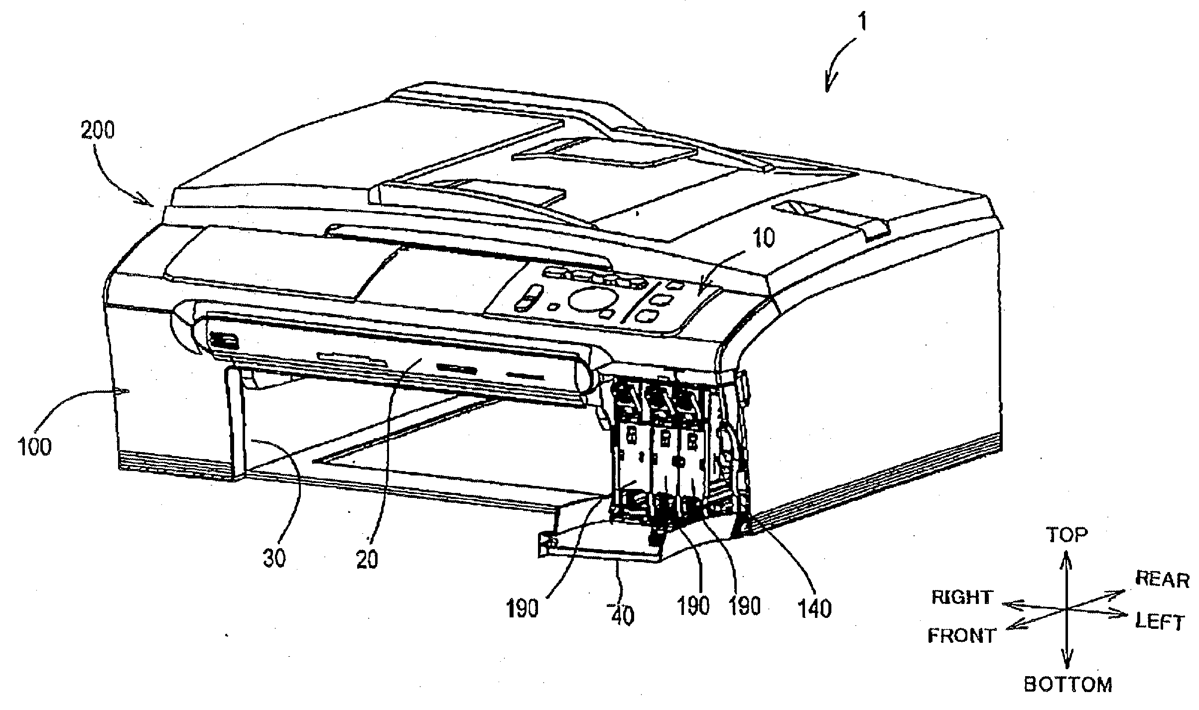
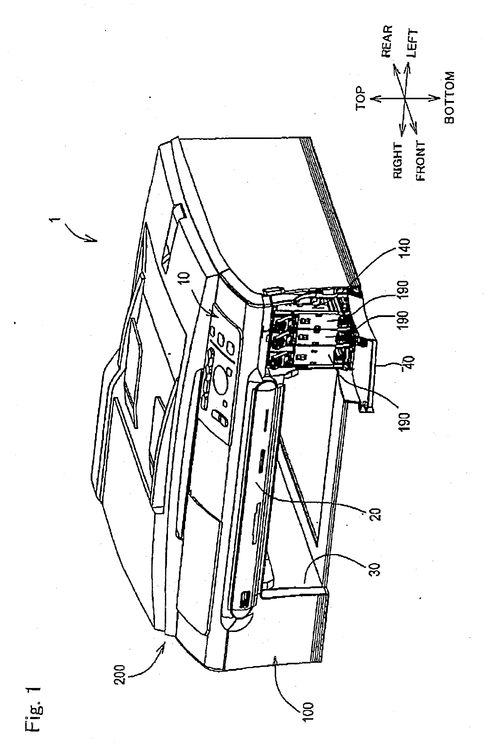
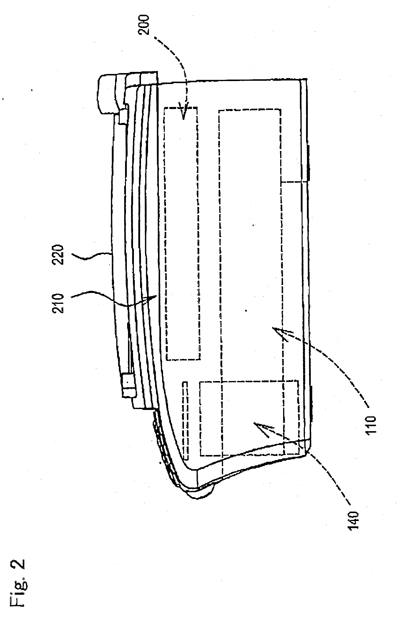
[0066]Hereinafter, embodiments to which the present invention is applied are described in conjunction with drawings. Here, the embodiments of the present invention are not limited to the embodiments described later and various modifications are considered without departing from a technical scope of the present invention.

[0067]In the embodiments, an ink jet recording apparatus according to the present invention is applied to a so-called multi-functional device having a printer function, a scanner function, a copier function, a facsimile function and the like.

[0068]A first embodiment of the invention will be described. Here, the multi-functional device according to the first embodiment is connected to a computer so as to record an image containing characters to a recording medium such as a recording sheet or an OHP sheet (hereinafter referred to as a recording sheet) based on image data or document data transmitted from the computer. The multi-functional device is connected to an exte...


PUM


Abstract

The present invention realizes the miniaturization of an ink jet recording apparatus by improving the tube arrangement (pull-around) structure. A flow passage of ink supplied from an ink cartridge is turned by approximately 90° using an elbow member, and ink tubes which are connected to the elbow member are arranged (pulled around) to extend toward an image recording part through gaps defined between a plurality of atmospheric-pressure introducing sleeves along an outer wall of the cartridge casing. Due to such an arrangement, compared to a case in which the ink flow passage is turned by approximately 90° using the flexibility of the ink tubes, it is possible to turn the ink tubes with a remarkably large radius of curvature and, at the same time, it is possible to decrease a size of a gap defined between the outer wall of the cartridge casing and other equipment such as a waste ink box. Accordingly, the present invention can realize the further miniaturization of a multi-functional device.

Description

CROSS-REFERENCE TO RELATED APPLICATIONS[0001]This application claims priority from Japanese Patent Application No. 2006-098206 filed on Mar. 31, 2007, the entire subject matter of which is incorporated herein by reference.BACKGROUND OF THE INVENTION[0002]1. Field of the Invention[0003]Illustrative aspects of the present invention relate to an ink jet recording apparatus (ink jet printer) which realizes the miniaturization thereof by improving the arrangement (particularly the arrangement of ink tubes) which supplies ink to recording heads.[0004]2. Description of the Related Art[0005]Ink jet recording apparatuses are, as being well known, configured to form an image on a recording medium such as a recording paper by ejecting ink droplets toward the recording medium using a recording head.[0006]For example, an ink jet recording apparatus described in patent document 1 supplies ink filled in an ink cartridge to a recording head through a tube having flexibility and performs printing wh...

Claims


Application Information

Patent Timeline
IPC IPC(8): B41J2/175
CPCB41J2/17509B41J2/17556B41J2/17553B41J2/17513
Inventor YANO, HIROYASU
Owner BROTHER KOGYO KK
Learn More