
Rear projection display apparatus

a rear projection display and display device technology, applied in the field of can solve the problems of trapezoidal distortion of images projected on screens by rear projection display devices, complicated adjustment of image positions, cumbersome, etc., and achieve the effect of correcting rotational distortion of images

Inactive Publication Date: 2007-10-04
SONY CORP
View PDF11 Cites 5 Cited by
  • Summary
  • Abstract
  • Description
  • Claims
  • Application Information

AI Technical Summary

Benefits of technology

[0014]Therefore, according to the embodiments of the present invention, it is desirable to provide a rear projection display apparatus which includes an adjustment mechanism by which trapezoidal distortion or rotational distortion of an image on a screen can be corrected simply and readily.
[0015]According to the present invention, there is provided a rear projection display apparatus including a housing, a screen provided on the front face of the housing, a mirror provided at a predetermined position in the inside of the housing and configured to reflect image light toward the screen, an optical unit including a projection lens configured to project the image light toward the mirror and an image apparatus configured to output the image light to the projection lens, a light source configured to supply a flux of light to the optical unit, and an optical device mounting plate having an upper face on which the optical unit is mounted and provided in a cantilever fashion on a wall provided on the inner side of a lower portion of the front face of the housing, the optical device mounting plate being capable of being deformed, when force is applied thereto, to vary an optical axis of the image light to be projected from the projection lens thereby to correct distortion of an image to be displayed on the screen.
[0016]In the rear projection display apparatus, if force is applied to the optical device mounting plate to deform the same, then the upper face of the optical device mounting plate is inclined to change the angle of the optical axis of the optical unit. Consequently, the center of the projected image can be moved in the upward or downward direction in response to the deformed state of the optical device mounting plate thereby to correct trapezoidal distortion. Or, the projected image can be rotated around the center thereof thereby to correct rotational distortion of the image.

Problems solved by technology

An image projected on a screen by a rear projection display apparatus is likely to suffer from trapezoidal distortion wherein the image is distorted into a trapezoidal shape or rotational distortion wherein the image is rotated around the center of the screen.
Therefore, the rear projector of the type described is disadvantageous in that the adjustment of the image position is complicated and cumbersome.
Therefore, the rear projector is disadvantageous in that, although it can correct trapezoidal distortion, it may not adjust rotational distortion of the image.
The rear projector is disadvantageous also in that, since the adjuster member is moved back and forth from the rear face side of the apparatus to adjust the image, it is inferior in operability in that it is not easy to perform the adjustment while the image is visually confirmed.

Method used


Image

  • Rear projection display apparatus
  • Rear projection display apparatus
  • Rear projection display apparatus

Examples


Embodiment Construction

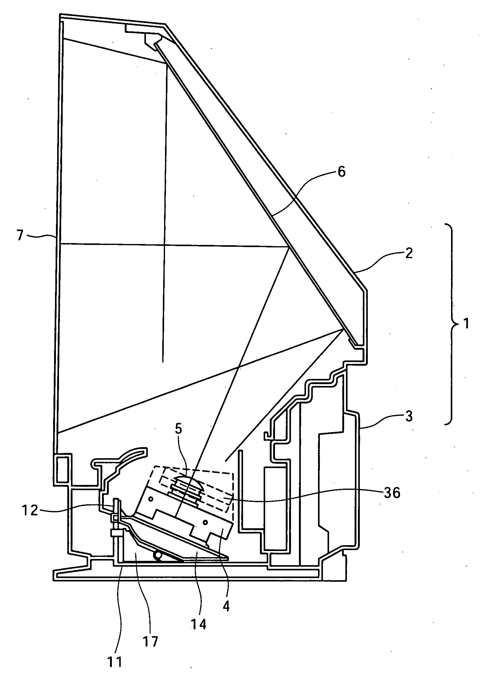
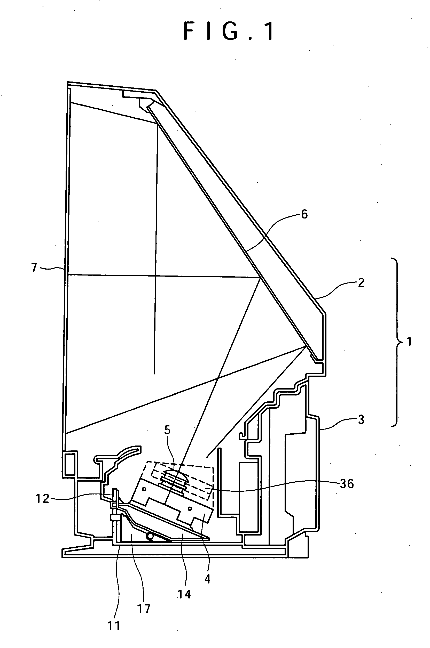
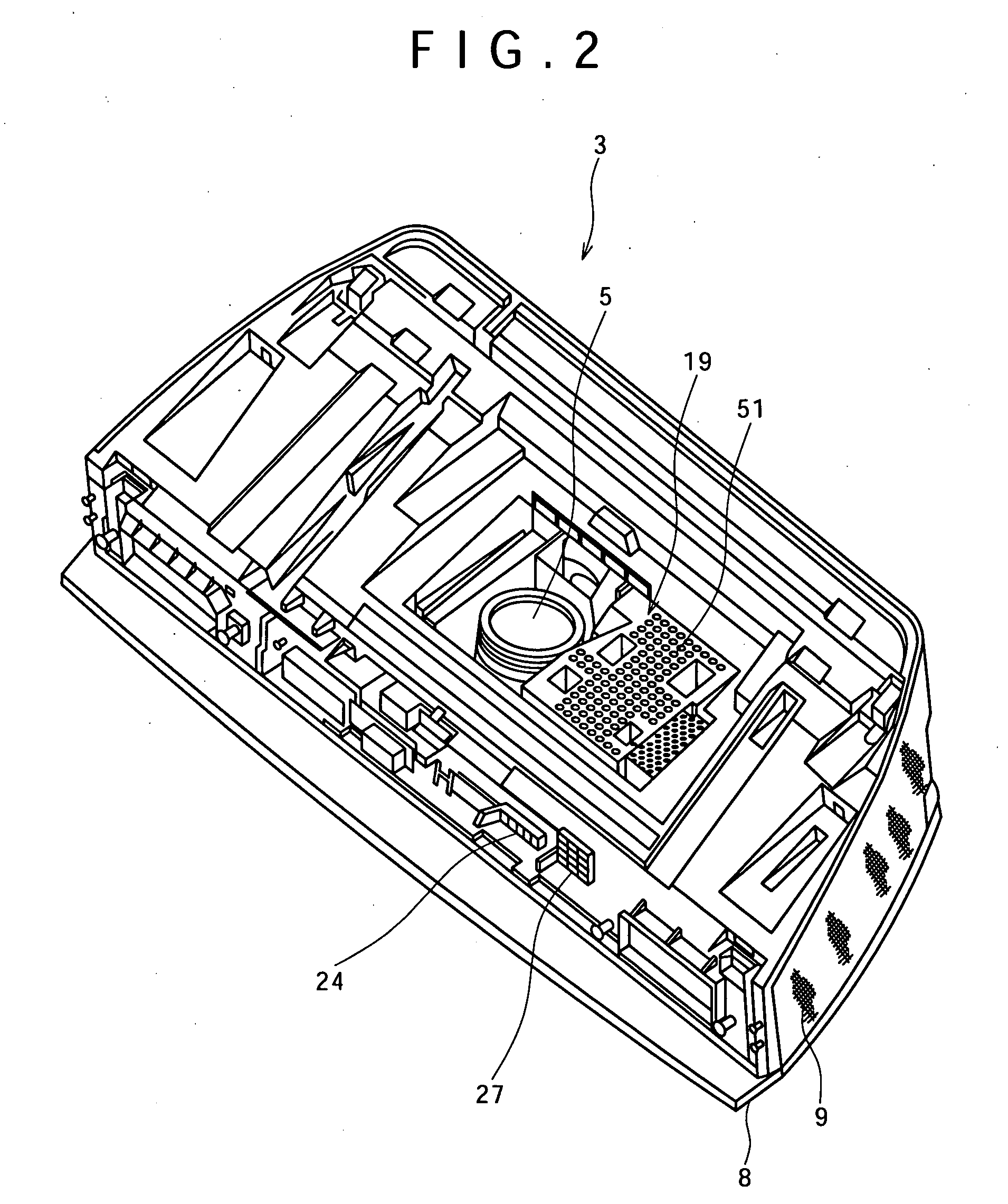
[0042]FIG. 1 is a schematic view showing an internal configuration of an entire rear projection display apparatus to which the present invention is applied, and FIG. 2 is a perspective view of a bottom cabinet of the rear projection display apparatus.

[0043]Referring first to FIG. 1, the rear projection display apparatus includes a cabinet 1 serving as a housing thereof. The cabinet 1 has a two-piece configuration including a top cabinet 2 shown on the upper side in FIG. 1 and a bottom cabinet 3 shown on the lower side in FIG. 1. A reflecting mirror 6 and a screen 7 are provided on the top cabinet 2, and an optical unit 4 is disposed in the bottom cabinet 3. The optical unit 4 modulates a flux of light emitted from a light source not shown in the figure to form an optical image in response to image information and projects the optical image in an enlarged fashion from a projection lens 5. The optical image projected in an enlarged fashion from the projection lens 5 is reflected by th...


PUM


Abstract

Disclosed herein is a rear projection display apparatus, including: a housing; a screen provided on the front face of the housing; a mirror provided at a predetermined position in the inside of the housing and configured to reflect image light toward the screen; an optical unit including a projection lens configured to project the image light toward the mirror and an image apparatus configured to output the image light to the projection lens; a light source configured to supply a flux of light to the optical unit; and an optical device mounting plate having an upper face on which the optical unit is mounted and provided in a cantilever fashion on a wall provided on the inner side of a lower portion of the front face of the housing.

Description

CROSS REFERENCES TO RELATED APPLICATIONS[0001]The present invention contains subject matter related to Japanese Patent Application JP 2006-099646 filed in the Japanese Patent Office on Mar. 31, 2006, the entire contents of which being incorporated herein by reference.BACKGROUND OF THE INVENTION[0002]1. Field of the Invention[0003]This invention relates to a rear projection display apparatus which projects an image from the rear side of a screen to display the image on the screen.[0004]2. Description of the Related Art[0005]In a rear projection display apparatus which uses a screen of the transmission type, a flux of light from a light source is irradiated, for example, upon a liquid crystal panel of the transmission type. The light flux is modulated in accordance with image information by the transmission type liquid crystal panel and is then projected in an enlarged fashion by a projection lens. Then, the optical path of the projected light flux is changed by a reflecting mirror so...

Claims


Application Information

Patent Timeline
IPC IPC(8): G03B21/56G02F1/13G03B21/10G03B21/14H04N5/74
CPCG03B21/10G03B21/28G03B21/14G03B21/147G03B21/62
Inventor SUKO, NAOTOTOKUMI, ATSUSHIUTSUMI, KENICHIRONAKAMURA, MITSURU
Owner SONY CORP
Learn More