

Systems for providing backlight module with stacked light source
- Summary
- Abstract
- Description
- Claims
- Application Information
AI Technical Summary
Problems solved by technology
Method used
Image

Examples
first embodiment
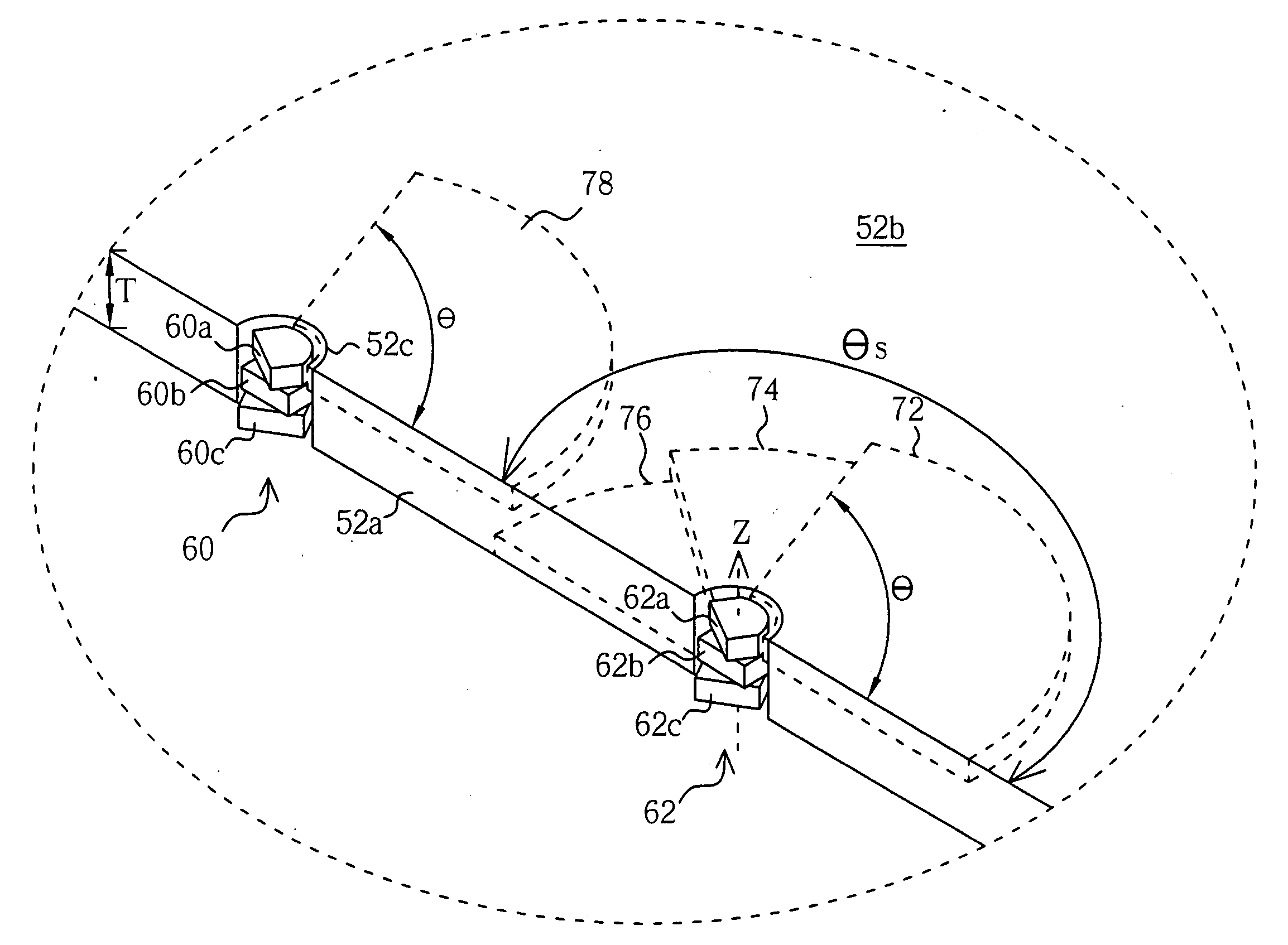
[0022] With reference to the drawings, FIGS. 3-5 are schematic diagrams of a system 50 providing a backlight module 51 according to the present invention. The backlight module 51 is applied to a display device, such as an LCD devices, and comprises a LGP 52, a plurality of optical films 54, 56, and a light source module 64, wherein the optical films 54 and 56 may be diffuser films or prisms. The LGP 52 has a wedge-shaped section view and comprises an incident surface 52a and an emitting surface 52b adjacent to the incident surface 52a. The light source module 64 comprises an array of light source sets 58, 60, 62 with respect to an overall edge of the LGP 52, the incident surface 52a. Each of the light source sets 58, 60, 62 comprises a plurality of stacked light sources, such as LEDs. For example, the light source set 62 includes a first LED 62a, a second LED 62b, and a third LED 62c. The first LED 62a is disposed above the second LED 62b, and the second LED 62b is sandwiched betwee...
second embodiment
[0029]FIG. 6 is an enlarge diagram of a light source set 62 of the present invention. For convenient illustration in FIG. 6, similar components retain the same label numbers that were used in FIG. 3. The light source set 62 comprises three stacked light sources, the first LED 62a, the second LED 62b, and the third LED 62c. However, the LEDs 62a, 62b, 62c are partially overlapped and rotated towards various directions. As shown in FIG. 6, the geometric centerline Za passing through the geometric center of the first LED 62a, the geometric centerline Zb of the second LED 62b, and the geometric centerline Zc of the third LED 62c are not positioned at a same point. In another word, the geometric centers of the first, second and third LEDs 62a, 62b, 62c are not overlapped. Accordingly, the emitting areas of the LEDs 62a, 62b, 62c can be shifted for making a fine tuning of the luminance of the LGP 52.
third embodiment
[0030] With reference to FIGS. 7-11, FIGS. 7-11 are schematic diagrams of the system providing a backlight module 100 according to the present invention.
[0031]FIG. 8 shows that the backlight module 100 can be incorporated into a display device 102, such as an LCD device, and controlled by a controller 152 coupled to the backlight module 100. Furthermore, the display device 102 can form a portion of a variety of electronic devices, represented by the numeral 104, such as a laptop computer, a mobile phone, a digital camera, a personal digital assistant (PDA), a desktop computer, a television, a car display or a portable DVD player. Therefore, a user of the display device 102 may control the electronic device 104 through the controller 152 to operate the backlight module 100. The backlight module 100 comprises a LGP 106 and a plurality of light sources. The light sources are LEDs, such as the LEDs 114, 118, 122, set on three different light source bases 116, 120, 124, wherein the LEDs ...
PUM
 Abstract
Description
Claims
Application Information