Periodic calibration for communication channels by drift tracking

a technology of drift tracking and communication channels, applied in the direction of synchronisation signal speed/phase control, transmission monitoring, receiver monitoring, etc., can solve the problems of system conditions changing, difficult to predict, and long patterns necessary to create worst-case inter-symbol interference or resonan

Active Publication Date: 2007-10-04
K MIZRA LLC
View PDF93 Cites 0 Cited by
  • Summary
  • Abstract
  • Description
  • Claims
  • Application Information

AI Technical Summary

Benefits of technology

[0012] Accordingly, the present invention provides a system and method for calibrating an operation value for a parameter of a communication channel, which allows for optimizing the operation value of the parameter, while efficiently accounting for drift of properties of the channel. A method for calibrating a communication channel, including a first component having a transmitter, a second component having a receiver, and a communication link coupling the first and second components, the communication channel having a parameter with an operation value determined by calibration, comprises establishing an operation value for a parameter of the communication channel; executing a drift calibration sequence, from time to time, to determine a drift value for the parameter of the communication channel, wherein drift calibration sequence comprises an algorithm different than used to establish the operation value; and updating the operation value in response to the drift value. In embodiments of the invention, the operation value is established by executing a first calibration sequence to set the operation value of the parameter of the communication channel, and wherein the drift calibration sequence utilizes less resources of the communication channel than the first calibration sequence. The first calibration sequence is executed, such as upon initialization of a system, to establish the operation value, which utilizes an algorithm that the designer intends to be exhaustive so that a suitable operation value can be determined for most conditions in which the system is designed to operate. A second calibration sequence is executed to determine a drift value in the parameter, and to update the operation value in response to the drift value. The second calibration sequence is executed from time to time during normal operation of the communication channel, and utilizes less resources of the communication channel than does the first calibration sequence. In one embodiment, the first calibration sequence for measurement of the operation value utilizes a long calibration pattern, such a data set including a code or codes which includes more than 200 bits, a code greater than 30 bytes, and a code based on a pseudorandom bit sequence having a length of 2N−1 bits, where N is equal to or greater than 7. The second calibration sequence utilizes a short calibration pattern, such as a fixed code less than 130 bits, such as less than or equal to 16 bytes, and for example as short as 2 bytes long. Thus in embodiments of the invention, the first calibration sequence utilizes many relatively short codes, or combinations of relatively short and longer codes, while the second calibration sequence uses one short code, or a few short codes where the total number of bits used in the second sequence is substantially less than the total number of bits used in the first sequence.

Problems solved by technology

In addition to the uncertainty of these variables, the patterns necessary to create worst-case inter-symbol interference or resonance can be very long, and are difficult to predict.
However, during normal operation, system conditions will change.
Although the calibration sequences can be run periodically to adjust for drift, the length and complexity of the patterns and the algorithms used in the sequences interfere with mission-critical operations of the system.
This creates at least two significant problems.
First, performance is reduced, in general.

Method used


Image

  • Periodic calibration for communication channels by drift tracking
  • Periodic calibration for communication channels by drift tracking
  • Periodic calibration for communication channels by drift tracking

Examples


Embodiment Construction

[0054] A detailed description of embodiments of the present invention is provided with reference to the Figures.

Transmitter and Receiver Timing Parameters

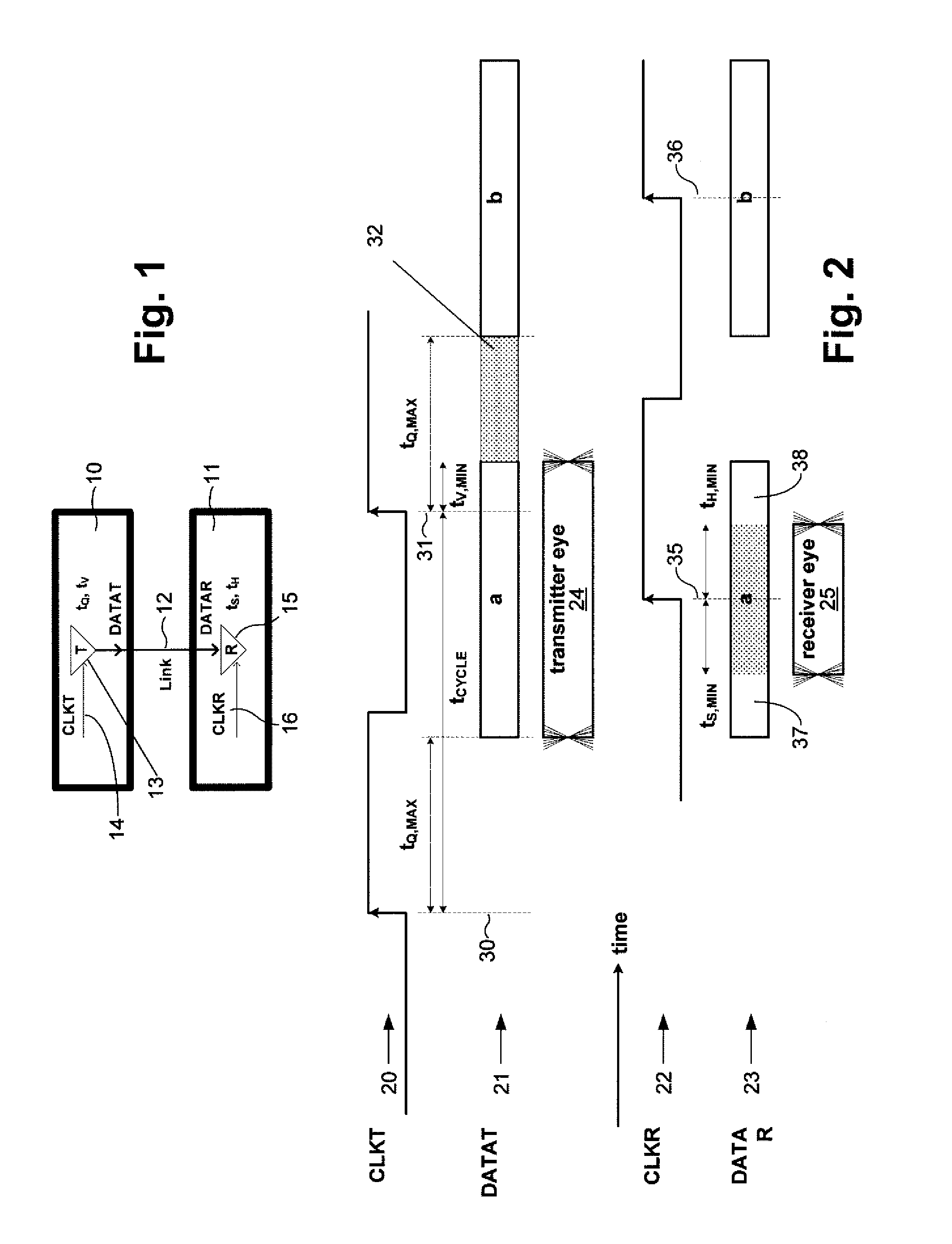
[0055]FIG. 1 shows two components 10, 11 connected with an interconnection medium, referred to as Link 12. One has a transmitter circuit 13 which drives symbols (bits) on Link 12 typically in response to rising-edge timing events on the internal CLKT signal 14. This series of bits forms signal DATAT. The other component 11 has a receiver circuit 15 which samples symbols (bits) on Link 12 typically in response to rising-edge timing events on the internal CLKR signal 16. This series of bits forms signal DATAR. The DATAT and DATAR signals are related; DATAR is an attenuated, time-delayed copy of DATAT. The attenuation and time-delay occur as the signal wavefronts propagate along the interconnection medium of Link 12. The communication channel comprising transmitter 13, link 12 and receiver 15 can be characterized by a plurality of ...


PUM


Abstract

A method and system that provides for execution of a first calibration sequence, such as upon initialization of a system, to establish an operation value, which utilizes an algorithm intended to be exhaustive, and executing a second calibration sequence from time to time, to measure drift in the parameters and to update the operation value in response to the measured drift. The second calibration sequence utilizes less resources of the communication channel than does the first calibration sequence. In one embodiment, the first calibration sequence for measurement and convergence on the operation value utilizes long calibration patterns, such as codes that are greater than 30 bytes, or pseudorandom bit sequences having lengths of 2N−1 bits, where N is equal to or greater than 7, while the second calibration sequence utilizes short calibration patterns, such as is fixed codes less than 16 bytes, and for example as short as 2 bytes long.

Description

CROSS REFERENCE TO RELATED APPLICATIONS [0001] The present application is a continuation of co-pending U.S. patent application Ser. No. 10 / 766,761, filed 28 Jan. 2004, entitled PERIODIC CALIBRATION FOR COMMUNICATION CHANNELS BY DRIFT TRACKING; which prior application is incorporated herein by reference.BACKGROUND OF THE INVENTION [0002] 1. Field of the Invention [0003] The present invention relates to the calibration of communication channel parameters in systems, including mesochronous systems, in which two (or more) components communicate via an interconnection link; and to the calibration needed to account for drift of conditions related to such parameters during operation of the communication channels. [0004] 2. Description of Related Art [0005] In mesochronous communication channels, typically a reference clock provides frequency and phase information to the two components at either end of the link. A transmitter on one component and a receiver on another component each connect...

Claims


Application Information

Patent Timeline
Patent Type & Authority Applications(United States)
IPC IPC(8): H04B1/38H04L7/00H04L7/04H04L7/10H04L27/00
CPCH04L7/0004H04L7/043H04B17/0062H04L27/00H04B17/00H04L7/10H04B17/21H04B17/11H04L7/0016H04L7/0087
Inventor HAMPEL, CRAIG E.WARE, FREDERICK A.PEREGO, RICHARD E.
Owner K MIZRA LLC
Why Eureka
Try Eureka