Offset rolling shutter camera model, and applications thereof

a camera model and rolling shutter technology, applied in the field of projecting image data, can solve problems such as large computing resources, errors become apparent, and texture maps may not properly correspond to three-dimensional models

Active Publication Date: 2017-10-31
GOOGLE LLC
View PDF7 Cites 0 Cited by
  • Summary
  • Abstract
  • Description
  • Claims
  • Application Information

AI Technical Summary

Benefits of technology

[0006]Embodiments efficiently account for variations in camera position across an image, when the image is texture mapped from a single position associated with the image. In a method embodiment, a first speed value corresponding to a speed of a camera when a first image was captured is received. The camera was in motion when the first image was captured. A plurality of time offset values are also received. Each time offset value corresponds to a pixel in the images captured by the first camera including the first image and represents a relative time when the camera captured the pixel. The camera captures different portions of the first image at different times. For respective pixels of the first image, a position in three-dimensional space at an intersection between a ray and a three-dimensional model representing content of the first image is determined. The ray is extended from a geocode of the first image based on a location of the pixel and camera parameters representing an orientation and focal length of the camera when it took the first image. An offset vector for the pixel is also determined. The offset vector corresponds to the first speed value and the time offset value corresponding to the pixel. Finally, the determined position is altered as specified by the offset vector. In this way, the altering corrects for a variation between the geocode of the first image and a position of the camera when the camera captured the pixel.

Problems solved by technology

However, even with these methods, different pixels of the resulting panoramic image may have different associated camera parameters.
These errors become apparent when the image is texture mapped onto a three dimensional model.
Because of the variation in camera position across an image, when the image is texture mapped from a single position associated with the image, the resulting texture map may not properly correspond to the three-dimensional model.
However, repeatedly projecting individual pixels may consume a large amount of computing resources, such as processing time and memory.

Method used


Image

  • Offset rolling shutter camera model, and applications thereof
  • Offset rolling shutter camera model, and applications thereof
  • Offset rolling shutter camera model, and applications thereof

Examples


Embodiment Construction

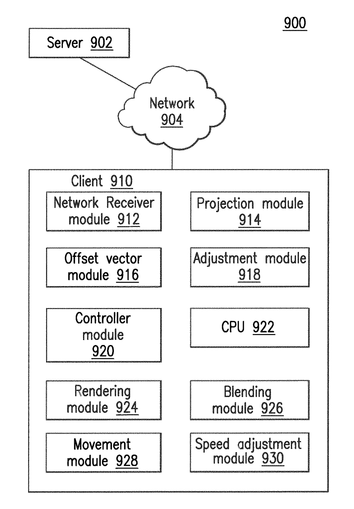
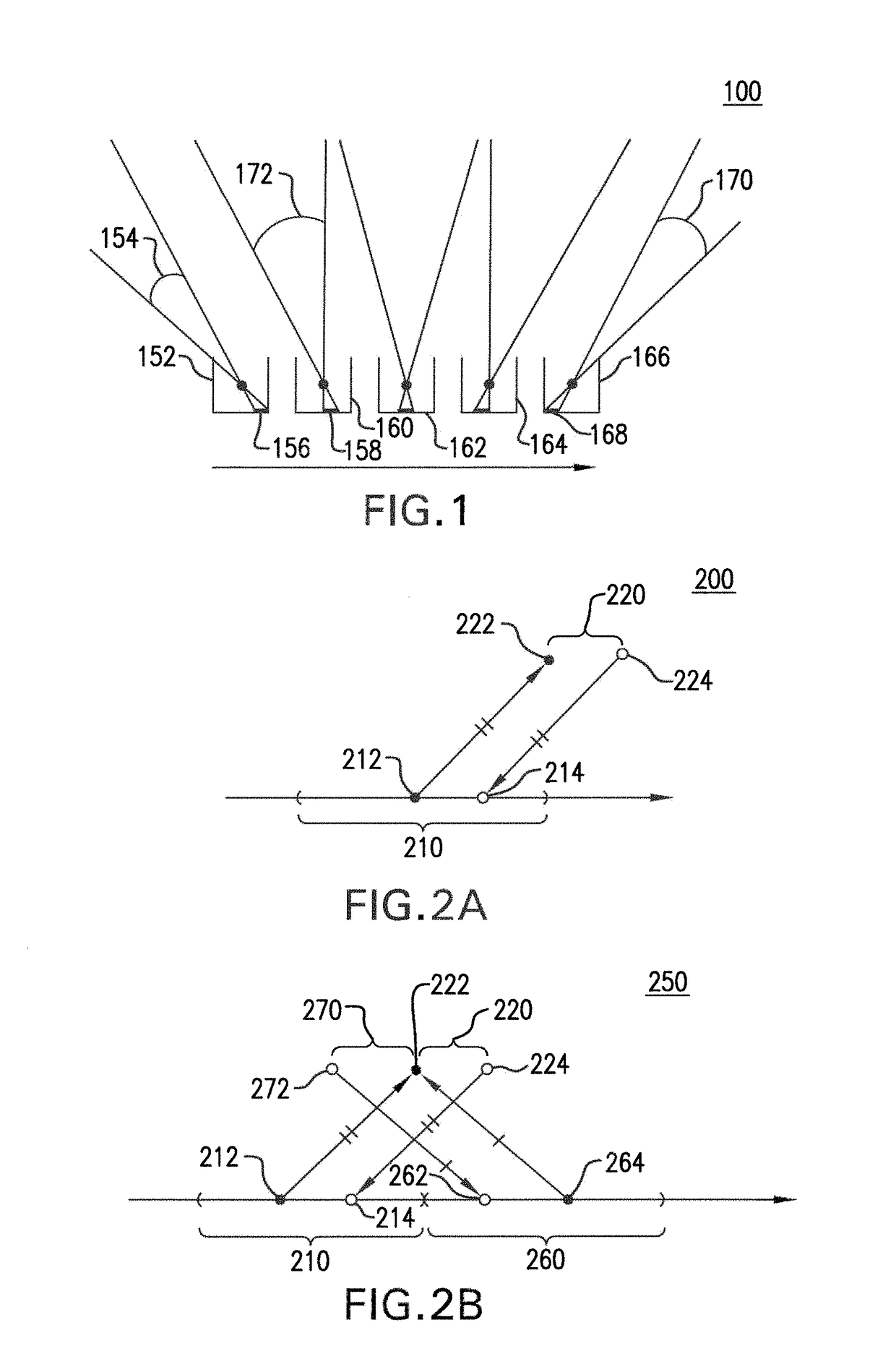
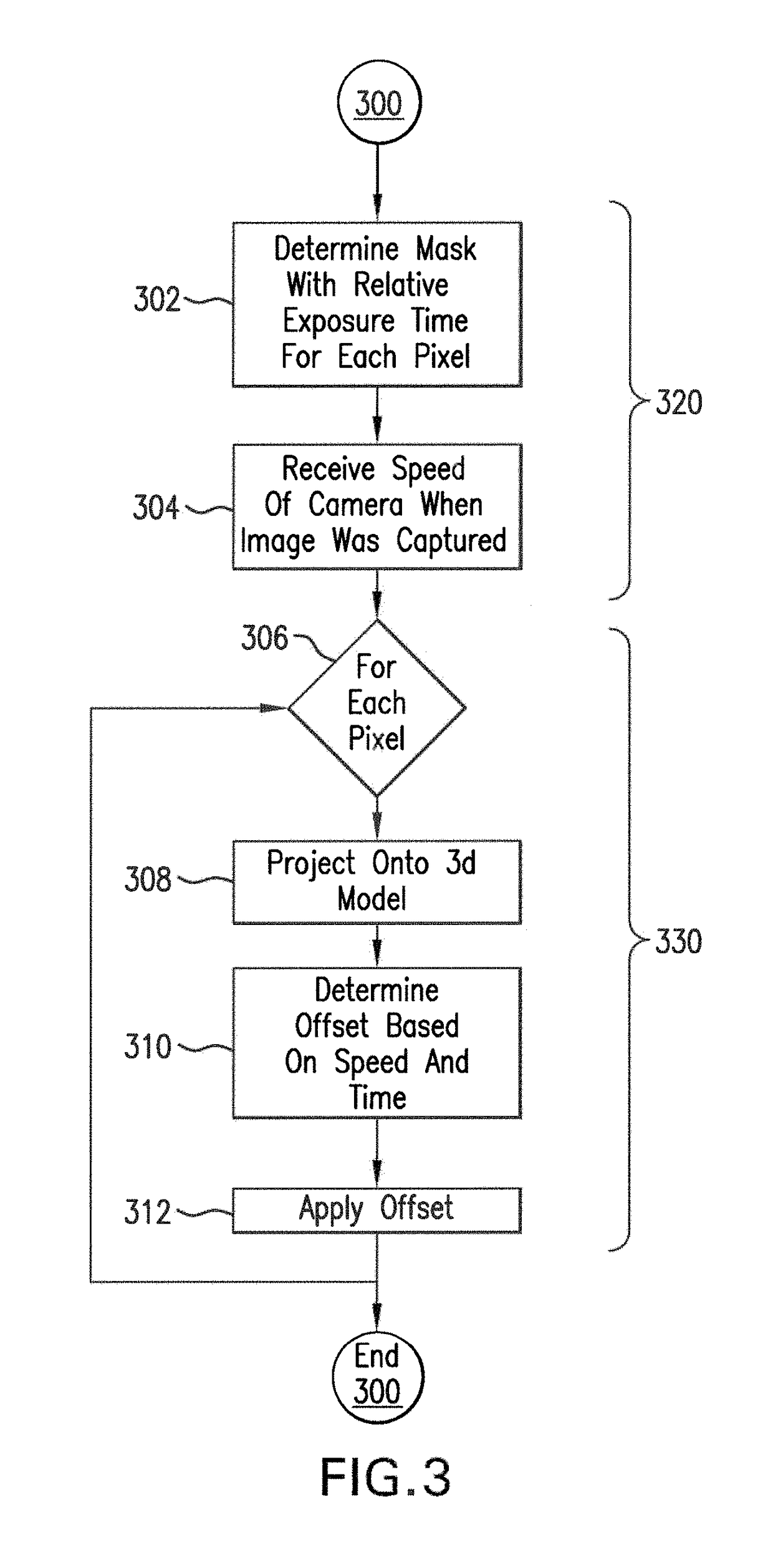
[0022]Embodiments efficiently account for variations in camera position across an image when the image is texture mapped from a single position associated with the image. To account for these variations, the position of projected pixels are offset by a distance determined according to a speed of the vehicle and a time offset of the pixel's exposure.

[0023]Some embodiments account for errors associated with use of a single geocode for a panorama that was captured from multiple positions over time. In an example operation, a client may receive, from a server, a mask corresponding to each panoramic image. Each mask may have a value corresponding to each pixel of the corresponding panoramic image. The value at each pixel may represent a time offset value indicating when that pixel was captured by the panoramic camera relative to other pixels in the image. In addition to the masks, the client may receive, from the server, a velocity value representing a speed that the panoramic camera was...


PUM


Abstract

Embodiments efficiently account for variations in camera position across an image, when the image is texture mapped from a single position associated with the image. In an embodiment, each pixel of an image is texture mapped to a three dimensional model. A time offset mask for the image and a value representing a speed of the camera are received. The time offset mask and speed values are used to create an offset mask. The offset mask is applied to the texture mapped model to correct for variations in camera position across an image.

Description

CROSS-REFERENCE TO RELATED APPLICATIONS[0001]The present application is a continuation of U.S. patent application Ser. No. 13 / 407,361, filed Feb. 28, 2012, the disclosure of which is incorporated herein by reference.BACKGROUNDField[0002]This application relates to projecting image data onto a three-dimensional model.Related Art[0003]Imaging systems exist that include more than one camera in a rosette formation attached to a vehicle. Those imaging systems may be used to capture panoramic images, for example, along a street. Each camera in the rosette formation includes an image sensor that converts an optical signal into an electrical signal to form an image. Two types of image sensors avoid the need for a mechanical shutter-an interline-shutter charge-coupled device (CCD) or a complementary metal oxide semiconductor (CMOS) sensor. The CMOS sensor typically has a rolling shutter, which exposes different lines of the scene at slightly different times, in a sequence that rolls across t...

Claims


Application Information

Patent Timeline
Patent Type & Authority Patents(United States)
IPC IPC(8): H04N13/02H04N13/00H04N5/232
CPCH04N5/23238H04N13/0007G06T5/50G06T2207/20221H04N13/106H04N23/661H04N23/698H04N25/531
Inventor ESTEBAN, CARLOS HERNANDEZANDERSON, ROBERT
Owner GOOGLE LLC
Why Eureka
Try Eureka