Image heating apparatus and image forming apparatus

a technology of heating apparatus and forming apparatus, which is applied in the direction of electrographic process apparatus, instruments, optics, etc., can solve the problems of limiting the total length of time the endless belt can be rotated, cracks in the surface layer of the endless belt, and the durability of the endless belt is reduced

Inactive Publication Date: 2007-10-04
CANON KK
View PDF8 Cites 25 Cited by
  • Summary
  • Abstract
  • Description
  • Claims
  • Application Information

AI Technical Summary

Problems solved by technology

Without being continuously run, the portion of the endless belt, which is facing the heating means, becomes substantially higher in temperature than the rest of the endless belt, which drastically reduces the endless belt in durability.
On the other hand, as an endless belt increases in the cumulative length of running time, cracks develop in the surface layer of the endless belt.
Thus, there is a limit to the total length of time the endless belt can be rotated (endless belt has limited life span).
Further, the speed at which the pressure belt is rotated while the fixing apparatus is kept on standby, is slower than that while an image is actually formed.
However, a fixing apparatus of the endless type, which employs a heating system which always (whether fixation belt is kept stationary or being rotated) heats its fixation belt only across the portion which faces its heating means, even while the fixing apparatus is on standby, suffers from the following problem.

Method used


Image

  • Image heating apparatus and image forming apparatus
  • Image heating apparatus and image forming apparatus
  • Image heating apparatus and image forming apparatus

Examples


embodiment 1

[0026]FIG. 1 is a sectional view of the image forming apparatus in this embodiment, and shows the general structure of the apparatus. This image forming apparatus is an electrophotographic multifunction full-color image forming apparatus which is capable of functioning as a printer, a copying machine, and a facsimile machine. First, the image forming portion of the apparatus will be described.

[0027] Designated by a referential number 1 is an image reading portion, which has: a glass platen la on which an original O (multicolor color image, for example) is to be placed; a movable optical system 1b; and a full-color sensor 1c (CCD) . The image reading portion 1 scans the original on the glass platen la, with the beam of light which the movable optical system 1b projects, and receives by the full-color sensor 1c, the light reflected by the surface of the original O. The full-color sensor 1c separates the reflected light it receives, into lights of the primary colors, and outputs signa...

embodiment 2

[0092] In the first embodiment described above, the length of the interval with which the belts 35 and 39 were rotationally driven in a standby period was set so that the thermo-switch as a safety apparatus did not react.

[0093] In this second preferred embodiment, the length of time the motors M1 and M2 for rotationally driving the belts 35 and 36 are kept stationary, that is, the length of time the belts 35 and 39 are kept stationary, is controlled according to the detected temperature of the fixation belt 35.

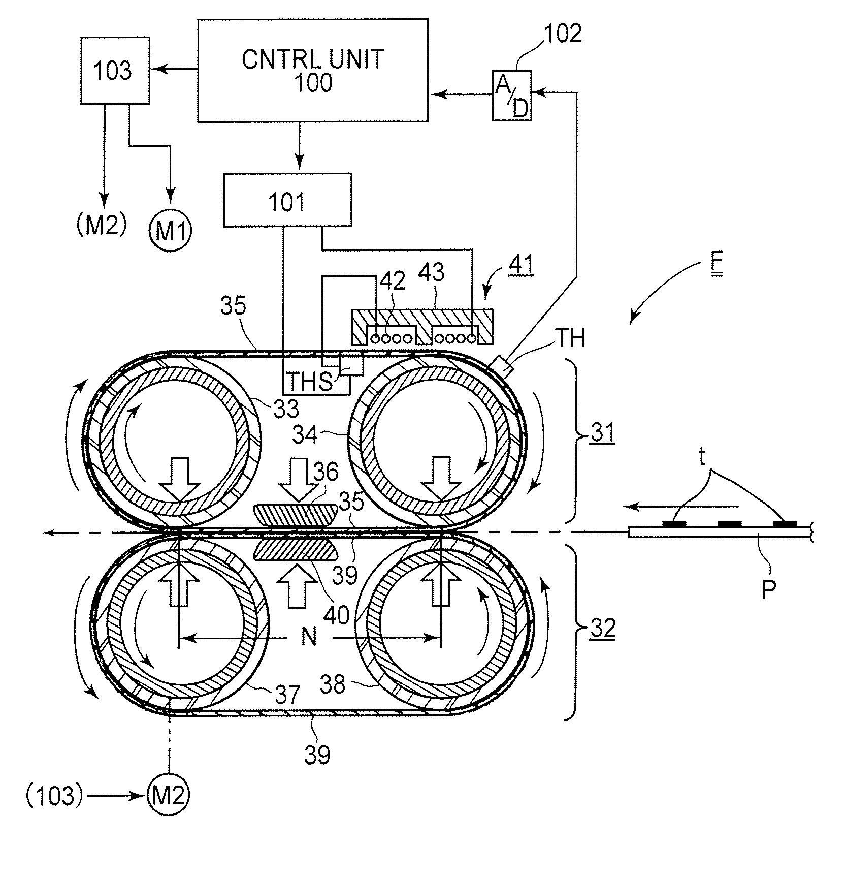
[0094]FIG. 8 is a block diagram of the motor controlling system in this embodiment. The temperature detecting means TH for detecting the temperature of the fixation belt 35 outputs voltage, the amplitude of which is proportional to the detected temperature of the fixation belt 35. This voltage is inputted into the A / D convertor 102. The A / D converter 102 converts this inputted voltage which indicates the detected temperature of the fixation belt 35 into a digital signal, and...

embodiment 3

[0098] In the second preferred embodiment described above, the length of time the motors M1 and M2 for rotationally driving the belts 35 and 39 are kept stationary in a standby period was controlled according to the temperature of the fixation belt 35.

[0099] In this embodiment, the length of time the motors M1 and M2 are driven each time in a standby period is also controlled according to the temperature of the fixation belt 35.

[0100] The control unit 100 controls the motor driving circuit 103 according to the flowchart in FIG. 10. That is, in Step S201, it is checked whether or not the image forming apparatus is on standby. If it is determined that the image forming apparatus is on standby, the fixation motors M1 and M2 are stopped in Step S202. Next, the temperature of the fixation belt 35 is detected in Step S203. If it is no less than 225° C., the fixation motors M1 and M2 are driven in Step S204. If it is not, the fixation motors M1 and M2 are kept stationary until it becomes...


PUM


Abstract

An image heating apparatus comprising an endless belt for heating an image on a recording material; heating means for heating a part of the endless belt; driving means for rotating the belt; a first contact member for contacting an inner surface of the belt; stand-by control means operable in a stop period in which the heating means effects heating with the belt at rest and in a rotation period in which the belt is rotated; and drive stop control means for stopping, upon stoppage of rotation of the in the rotation period, the endless belt at such a position that contact member contacts at least a part of such a portion of the endless belt as has been opposed to the heating means in a previous stop period.

Description

FIELD OF THE INVENTION AND RELATED ART [0001] The present invention relates to a preferable image heating apparatus as a fixing apparatus mountable in an image forming apparatus, such as a copying machine, a printer, a facsimile machine, etc. More specifically, it relates to an image heating apparatus of the so-called belt type. [0002] An image forming apparatus of the belt type has: an endless belt; a driving means for rotationally driving the endless belt; a heating means for applying heat to the portion of the endless belt, which is moving through the heating range of the heating means. It is an apparatus structured so that the image on recording medium can be heated by placing the recording medium in contact with the endless belt which is heated by the heating means while being rotationally driven by the driving means. [0003] The endless belt is heated by the heating means, only across the area which is moving through the heating range of the heating means. However, since the en...

Claims


Application Information

Patent Timeline
Patent Type & Authority Applications(United States)
IPC IPC(8): G03G15/20
CPCG03G2215/2016G03G15/2039G03G2215/2022
Inventor NOGUCHI, JUNICHI
Owner CANON KK
Why Eureka
Try Eureka