Motor assembly structure

a technology of motor assembly and assembly structure, which is applied in the direction of positive displacement liquid engine, pump, machine/engine, etc., can solve the problems of high manufacturing cost, complicated assembly of above components, and high manufacturing cost, so as to facilitate the assembly procedure of the motor assembly structure, and reduce the number of components.

Inactive Publication Date: 2007-10-04
KAI ZHAO TECH
View PDF5 Cites 19 Cited by
  • Summary
  • Abstract
  • Description
  • Claims
  • Application Information

AI Technical Summary

Benefits of technology

[0005] It is therefore a primary object of the present invention to provide a motor assembly structure including a first bracket and a second bracket which together form a coil unit. The first bracket has a hub integrally extending from the first bracket into the second bracket. The first bracket itself integrally has a hub so that an operator only needs to assemble the first and second brackets to fix the silicon steel plate unit. Therefore, the number of the components is reduced and the tolerance of the assembly of the components is minified. Also, the assembling procedure of the motor assembly structure is facilitated.

Problems solved by technology

The assembly of the above components is complicated.
The above assembling procedure is quite time-consuming.
Moreover, the conventional locator assembly includes numerous components so that the manufacturing cost is high.
These components are mass-produced and it is hard to precisely manufacture every components.

Method used


Image

  • Motor assembly structure
  • Motor assembly structure
  • Motor assembly structure

Examples


Embodiment Construction

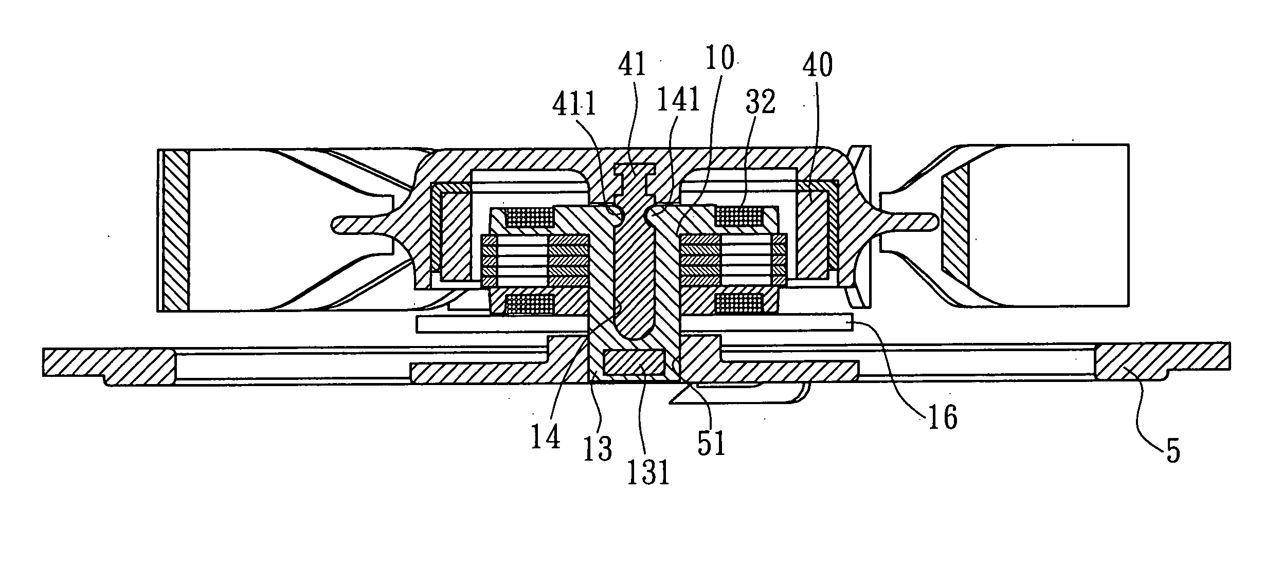
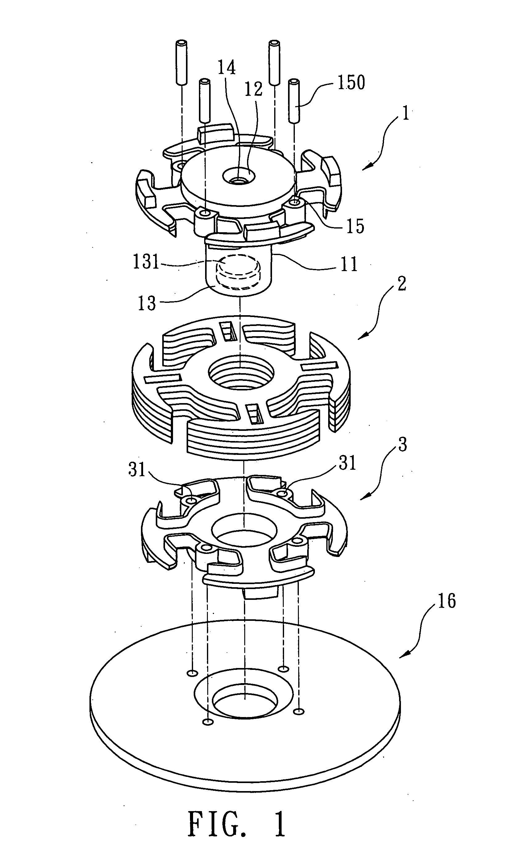
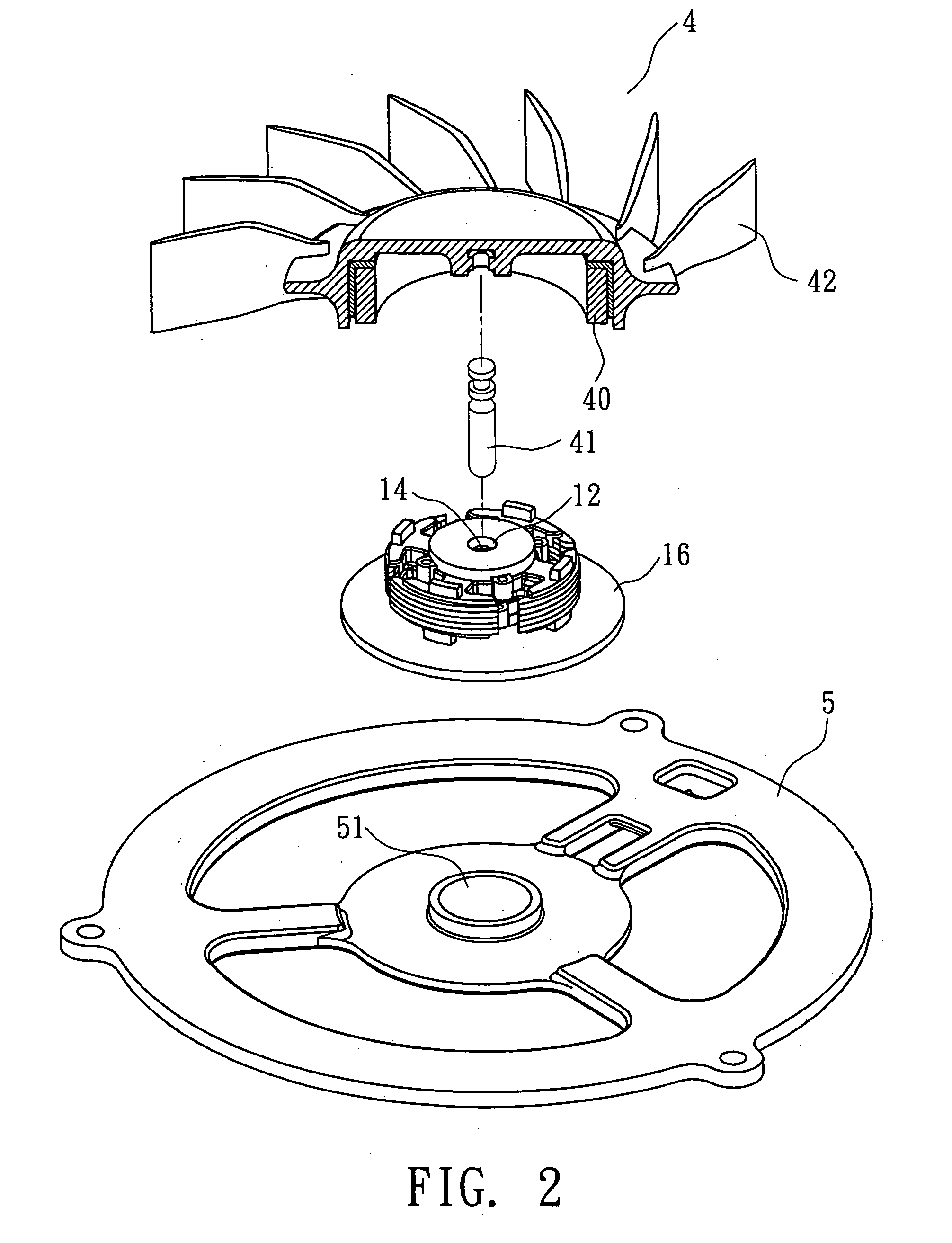
[0013] Please refer to FIGS. 1 to 3. The motor assembly structure of the present invention includes a first bracket 1, a silicon steel plate unit 2, a second bracket 3, a rotor 4 and a base seat 5.

[0014] The first bracket 1 has a hub 11 integrally extending from the first bracket 1 to the second bracket 3. The hub 11 has an opening 12 formed on a top face of the first bracket 1. The hub 11 has a connecting end 10 connected with the first bracket 1 and a close end 13 distal from the opening 12. The hub 11 is formed with a shaft cavity 14 communicating with the opening 12. In this embodiment, a magnet 131 is embedded in the close end 13 for attracting a central shaft 41 of the rotor 4 and keeping the central shaft 41 in a central position.

[0015] The silicon steel plate unit 2 is fitted around the hub 11 of the first bracket 1. In this embodiment, the silicon steel plate unit 2 is composed of multiple silicon steel plates which are piled up.

[0016] The silicon steel plate unit 2 is s...


PUM


Abstract

A motor assembly structure including a first bracket and a second bracket which together form a coil unit. The first bracket has a hub integrally extending from the first bracket into the second bracket. The motor assembly structure further includes a silicon steel plate unit fitted around the hub and sandwiched between the first bracket and the second bracket. The first bracket and the hub are integrally formed as a module so that the assembling procedure of the motor assembly structure is facilitated.

Description

BACKGROUND OF THE INVENTION [0001] The present invention is related to a motor assembly structure which can be easily assembled. [0002]FIG. 4 shows a conventional locator assembly including a bush 6, a coil unit 7 and a central shaft 8 drivingly connected with the vanes. The bush 6 is fitted in the coil unit 7. A bearing 60 is mounted in the bush 6 and the central shaft 8 is fitted through the bearing 60 as shown in FIG. 5. The vanes 81 are connected with one end of the central shaft 8 distal from the bush 6. The coil unit 7 serves to drive the vanes 81 to rotate. [0003] The assembly of the above components is complicated. First, the bush 6 must be fixed with a base seat 62. Then the entire coil unit 7 is fitted around the bush 6. Finally, the central shaft 8 is coupled with the bush 6. [0004] The above assembling procedure is quite time-consuming. Moreover, the conventional locator assembly includes numerous components so that the manufacturing cost is high. In addition, the compon...

Claims


Application Information

Patent Timeline
Patent Type & Authority Applications(United States)
IPC IPC(8): F04B17/00
CPCF04D25/0613H02K5/163H02K3/38H02K1/187
Inventor LIU, HSI-HUNG
Owner KAI ZHAO TECH
Why Eureka
Try Eureka