Plug-and socket connector

a plug-and-socket and socket technology, applied in the direction of securing/insulating coupling contact members, coupling device connections, connections effected by permanent deformation, etc., to achieve the effect of increasing air gap and creep path

Active Publication Date: 2007-10-04
ITT MFG ENTERPRISES LLC
View PDF3 Cites 40 Cited by
  • Summary
  • Abstract
  • Description
  • Claims
  • Application Information

AI Technical Summary

Benefits of technology

[0013]On the basis of the features of Claim 14, after final assembly, the first catch located in the wall is prevented from moving to the outside and thus from potentially releasing the connector contacts due to traction during the connecting or separating of two plug-and-socket connectors. The air gap and creep path are also increased as a result.

Problems solved by technology

If the subsequent, second locking process cannot take place, this is detected due to the incorrect position of the cover.

Method used


Image

  • Plug-and socket connector
  • Plug-and socket connector
  • Plug-and socket connector

Examples


Embodiment Construction

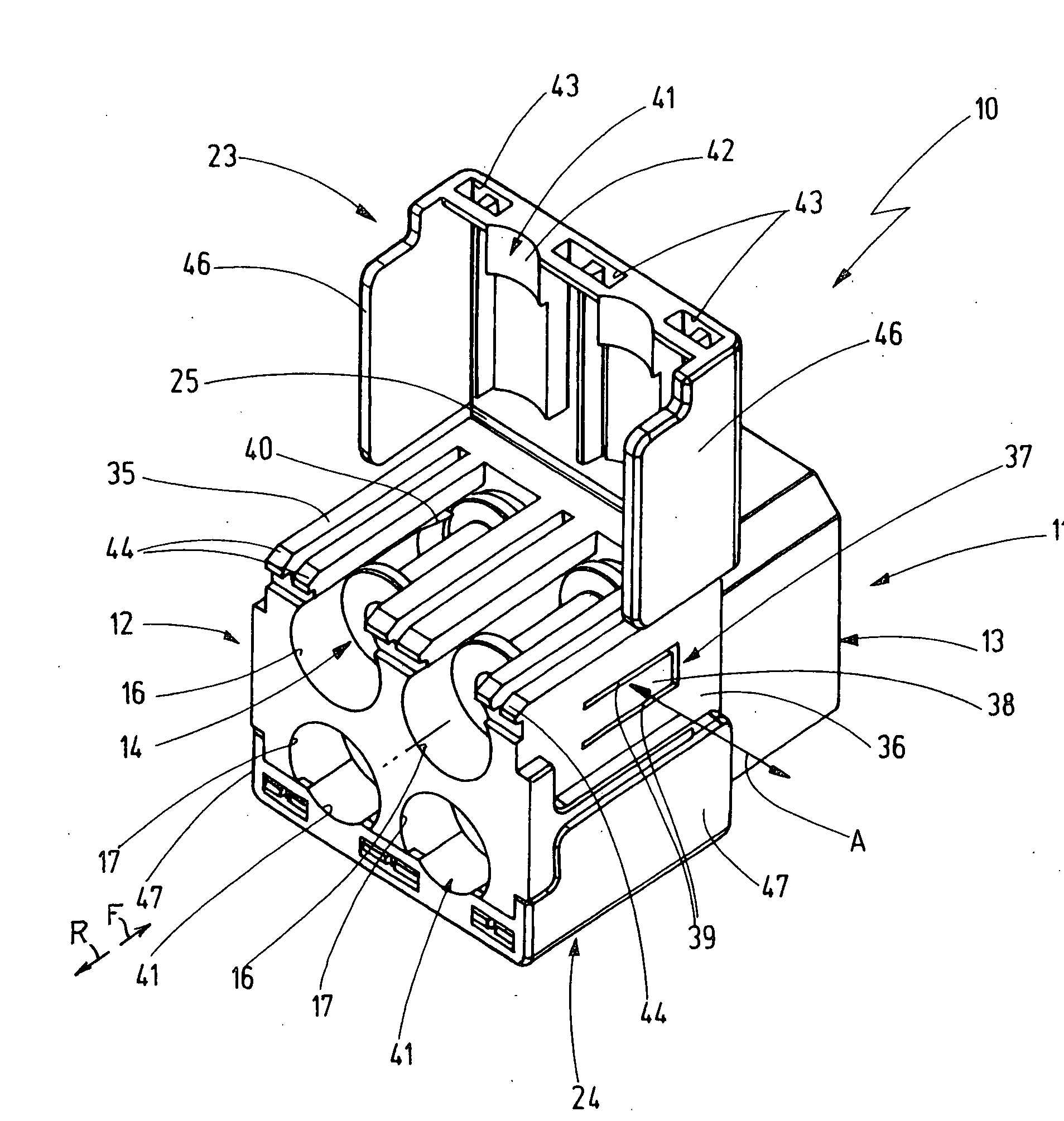
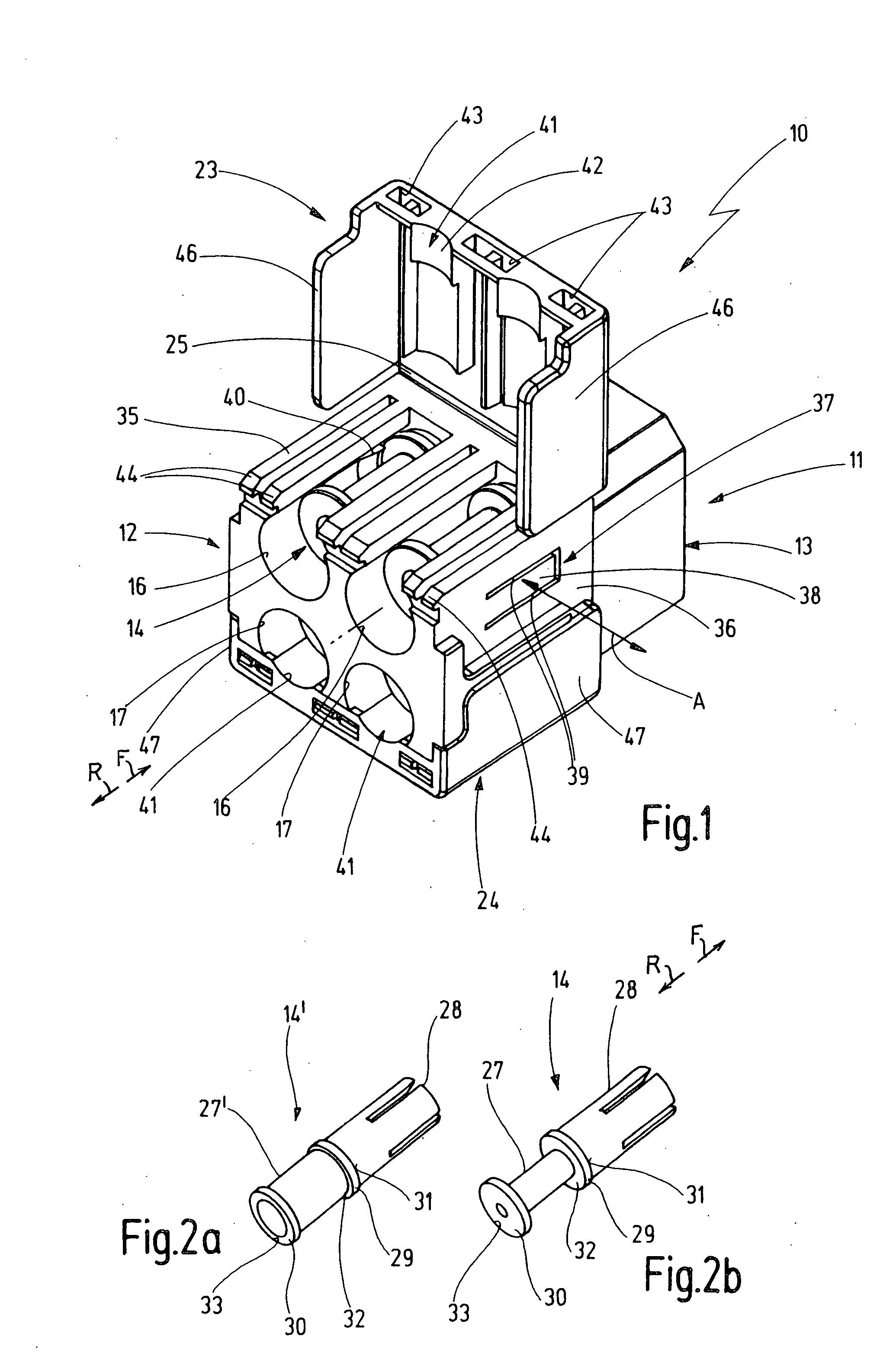
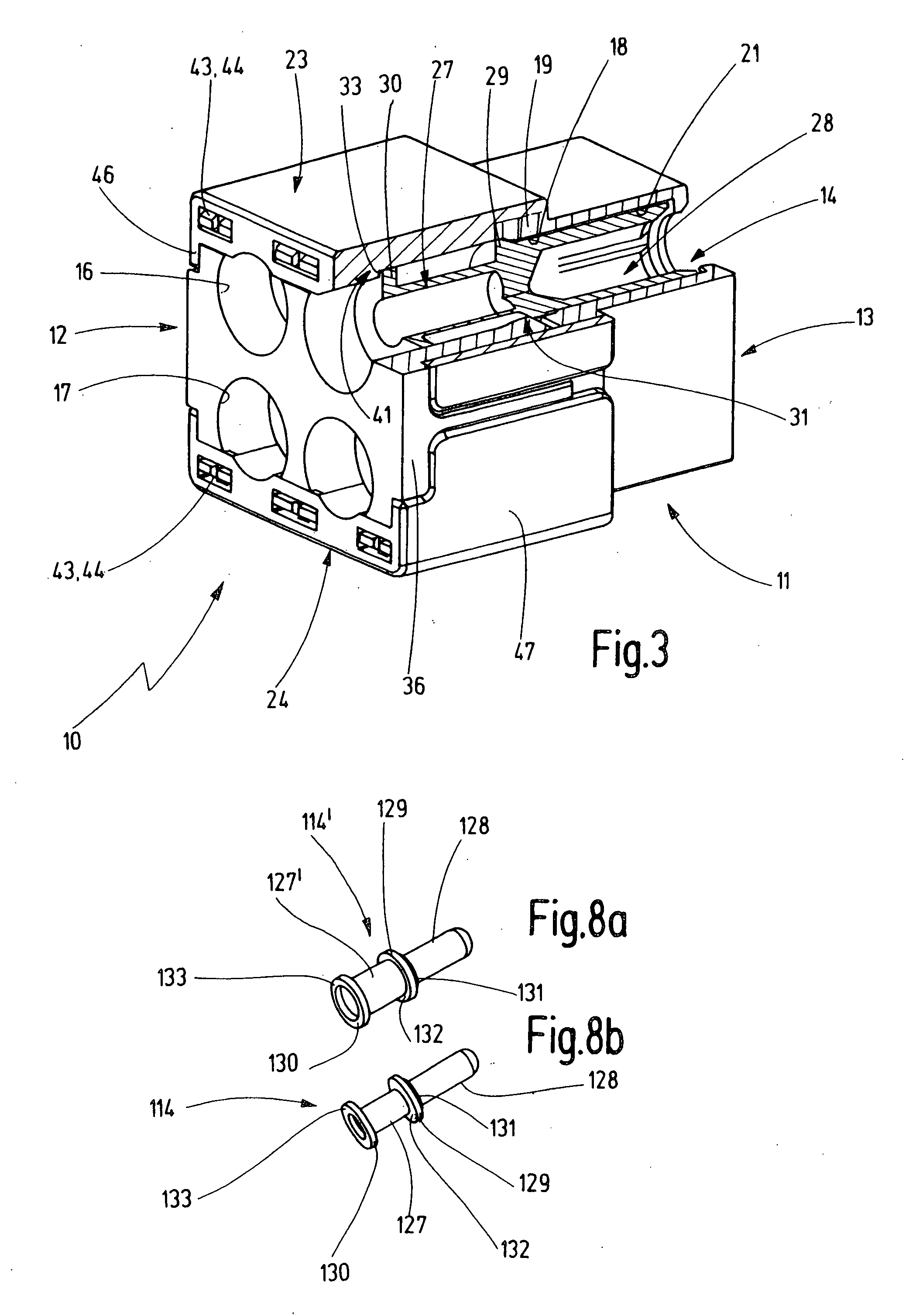
[0024]Electrical plug-and-socket connector 10, 10′ or 110 (FIGS. 1, 4, 6) depicted in the drawing in three embodiments can be connected, on the one hand, to electrical leads or wires (not shown) and each can be connected to a mating plug-and-socket connector (not shown) which also is or can be connected to electrical leads. For example, plug-and-socket connectors 10, 10′ in accordance with FIGS. 1 to 5 are each provided with a plastic housing 11, 11′ having a plug extension 13 and metal socket contacts 14. Also, electrical plug-and-socket connector 110 (FIG. 6) has a plastic housing 111, a socket extension 113, and metal male contacts 114. The corresponding mating electrical plug-and-socket connectors are similarly designed with respect to individual electrical plug-and-socket connectors 10, 10′, 110.

[0025]According to FIG. 1, electrical plug-and-socket connector 10 has a housing 11 made of plastic (non electrically conductive). The connector has a forward F plug extension 13 and a ...


PUM


Abstract

A plug-and-socket connector (10) has a plastic housing (11) that holds electrical male or female contacts (14) in boreholes (16, 17) next to each other, and whose forward end forms a plug extension (13) or as a socket extension (113) and whose rear end receives and locks the male or female contacts (14) in the housing (11). In a plug and socket connector (10) of this type, in order to lock the male or female contacts in two ways, independently of each other, in the plastic housing (11), at the same time permitting the plastic housing (11) to be shaped using injection molding technology in a relatively simple manner, it is provided that, for receiving a male or female contact (14), a first catch (37) protrudes in the area of each borehole (16, 17) located on the other, rear housing end (12, 112), said catch being arranged on a fixed wall (36) of the rear housing end and engaging a first collar (29) of the male or female contact (14) from behind, and a second catch (41, 51) is provided on a cover (23, 24) so as to allow the radially open rear housing end (12) to be closed and covered, said catch engaging the first collar (29) or a second collar (30) of the male or female contact (14) from behind.

Description

CROSS-REFERENCE TO RELATED APPLICATION[0001]Applicant claims priority from German patent application no. 10 2006 016 882.8-34 filed Apr. 4, 2006.BACKGROUND OF THE INVENTION[0002]The present invention relates to a plug-and-socket connector.[0003]In the case of familiar plug-and-socket connectors of this type, the male or female contact is inserted into the housing and is locked into place in one area. Because this male or female contact is inserted into the plastic housing manually, there is no guarantee that each of the male or female contacts will be locked in the correct position or even locked into place at all.[0004]It is therefore the objective of the present invention to create a plug-and-socket connector of the type mentioned above, in which it is undertaken to lock the male or female contacts in two ways, independently of each other, in the plastic housing, thus preventing any failure to lock from going undetected, at the same time making it possible to mold the plastic hous...

Claims


Application Information

Patent Timeline
Patent Type & Authority Applications(United States)
IPC IPC(8): H01R13/627
CPCH01R4/18H01R13/4361H01R13/42
Inventor SINGER, HELMUT
Owner ITT MFG ENTERPRISES LLC
Why Eureka
Try Eureka