Electric machine with a winding support assembly and a measuring system

a technology of winding support and measuring system, which is applied in the direction of windings, magnetic circuit rotating parts, magnetic circuit shape/form/construction, etc., can solve the problems of motor failure or destruction, motor failure or total destruction, and improper routing of lead-out wires, so as to reduce production time, eliminate assembly errors and eliminate mechanical and electrical damage risk. , the effect of reducing the production tim

Active Publication Date: 2009-03-10
SIEMENS AG
View PDF7 Cites 7 Cited by
  • Summary
  • Abstract
  • Description
  • Claims
  • Application Information

AI Technical Summary

Benefits of technology

[0011]The measuring system is thereby reliably secured in the wiring support assembly attached to the motor, i.e., fixedly embedded in the motor structure. The measuring system is hence protected by the wiring support assembly, so that the sensor can reliably operate even during strong shocks or vibrations.
[0012]In more complex winding arrangements, several support assemblies can optionally be arranged sequentially in the axial direction, which can prevent faults resulting from complex winding connections. In such case, the measuring system can be configured so that all winding systems can be monitored simultaneously.
[0013]Advantageously, the winding support assembly can also include a snap-on cover that can help increase the air gaps and leakage paths and therefore also increase the breakdown voltage. In addition, unattached wires, such as lead-out wires, can be secured in this manner. The cover may also provide strain relief for the electric supply wires in form of terminals or a meander-like wire placement.
[0022]The measuring system can then almost instantaneously provide a measurement value that is proportional to the actual temperature of the winding. Consequently, the warning temperature, i.e., the temperature at which a warning is sounded because the excess temperature could damage the winding and therefore also the motor, needs only be reduced slightly or not at all. Electric motors can then safely operate closer to their rated power limit.
[0023]According to another advantageous embodiment of the invention, the sensor can be encapsulated or sealed in the winding support assembly. In other words, the sensor can already be encapsulated in the winding support assembly of the motor during manufacture. The position of the sensors and their connection with the motor is then well defined, which not only significantly reduces the corresponding time constant, but also its variation due to manufacturing tolerances. The sensor can be located and encapsulated at the most suitable location for the parameter to be monitored.
[0024]In addition, the sensors need no longer be manually attached to the motor, which simplifies manufacture and reduces the production time, while also eliminating errors during assembly and the risk of mechanical and electrical damage to the sensors. In an alternative embodiment, sensors, such as temperature sensors, could also be attached to or encapsulated in the winding support by using a spring-like structure in order to ensure a reliable contact with the surface to be measured. Advantageously, sensors could also be attached to the bottom side of the winding support assembly between the winding support and the stator.

Problems solved by technology

Disadvantageously, the location of the lead-out wires and / or the end turns is fixed, while the lead-out wires are neither properly routed nor reliably connected.
The motor can fail or be destroyed if the allowable winding temperature is exceeded.
For example, if an air gap is created between the winding and the sensor, then the time constant of the protective circuits can change, so that the motor can be completely destroyed, for example as the result of a fire, before the protective circuit can respond to the increase in temperature.
Disadvantageously, however, the size of the gap is then not defined.
This changes the time constant of the protective circuit, which depends on the size of the gap, making the motor protection unreliable.

Method used


Image

  • Electric machine with a winding support assembly and a measuring system
  • Electric machine with a winding support assembly and a measuring system
  • Electric machine with a winding support assembly and a measuring system

Examples


Embodiment Construction

[0033]Throughout all the Figures, same or corresponding elements are generally indicated by same reference numerals. These depicted embodiments are to be understood as illustrative of the invention and not as limiting in any way. It should also be understood that the drawings are not necessarily to scale and that the embodiments are sometimes illustrated by graphic symbols, phantom lines, diagrammatic representations and fragmentary views. In certain instances, details which are not necessary for an understanding of the present invention or which render other details difficult to perceive may have been omitted.

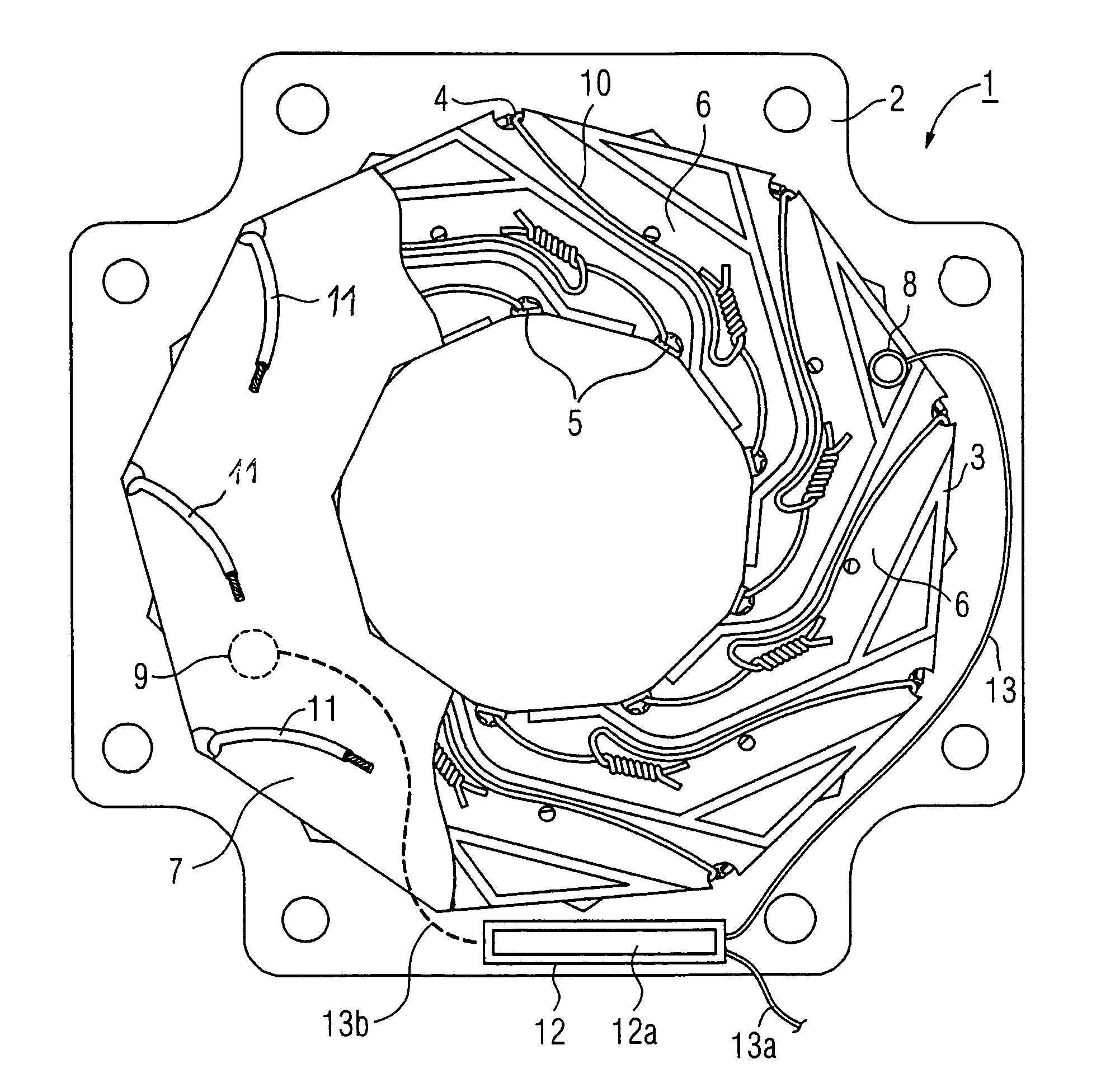
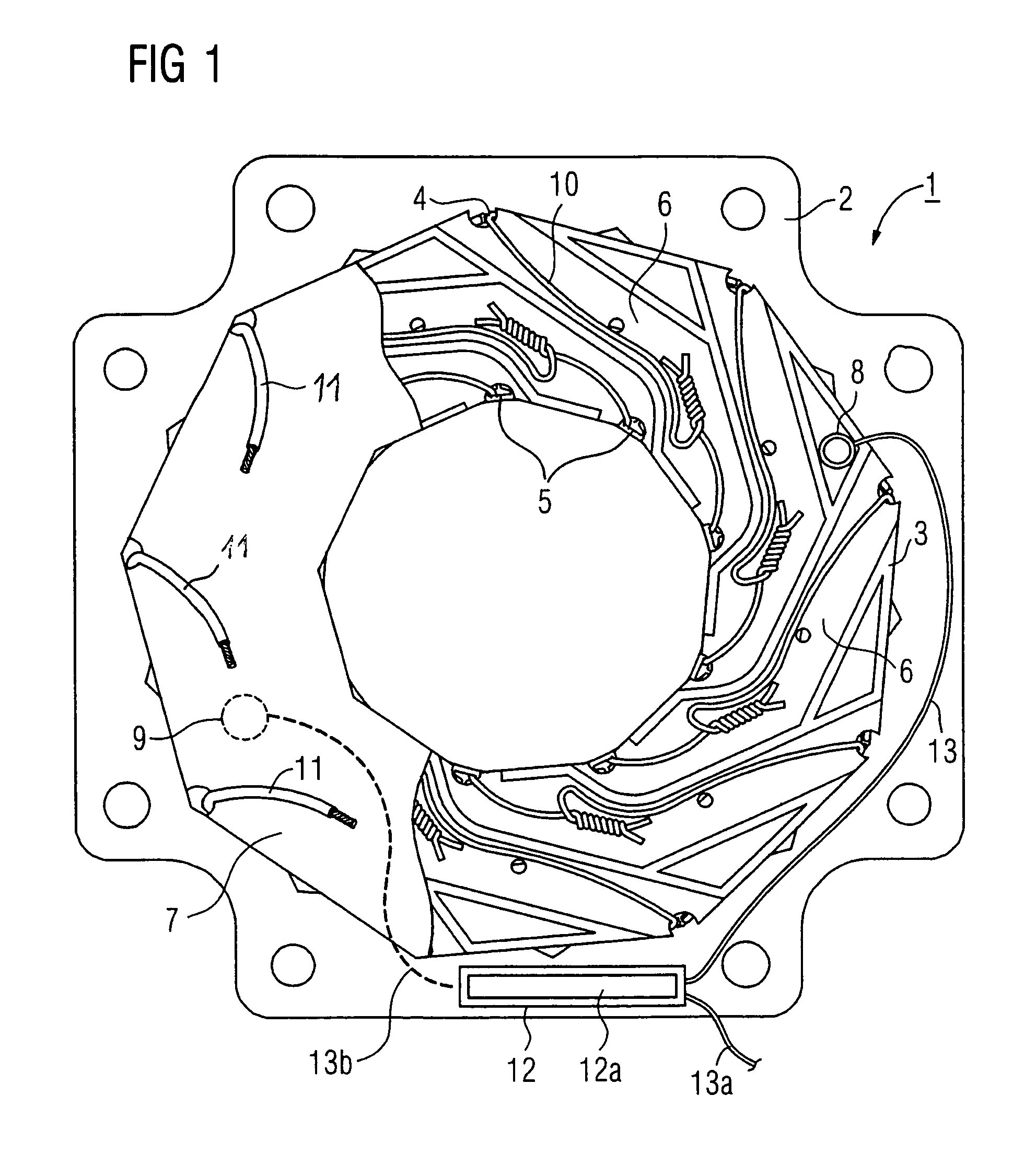
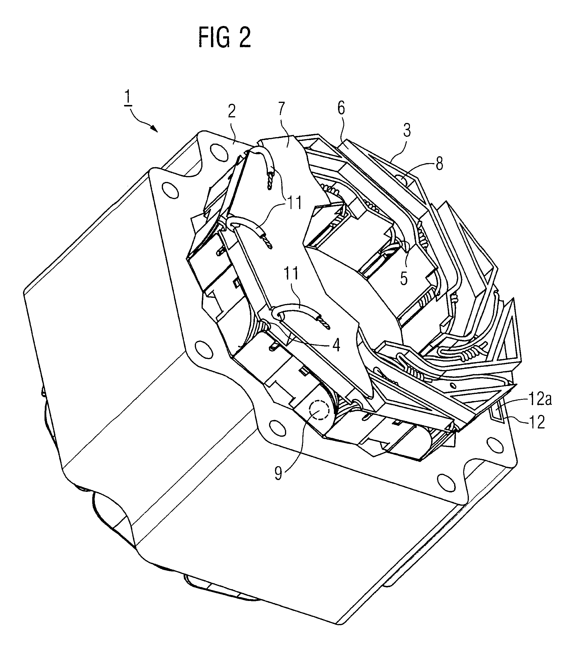
[0034]Turning now to the drawing, and in particular to FIG. 1, there is shown in a side view a stator 1 of an electric machine (not shown) with a stator housing 2 and a winding support assembly 3 disposed on an end face of the housing 2. The winding support assembly 3 is partially cut open and includes a cover 7, which is only shown in the left half of FIG. 1. Channels 6 of th...


PUM


Abstract

An electric machine, in particular a motor, includes a winding support assembly and a measuring system, preferably an infrared measuring system, The measuring system has at least one sensor and an evaluation unit, whereby the measuring system is integrated in the winding support assembly. The infrared sensor, which operates without making contact with the winding support assembly, provides almost instantaneously a measurement value that is proportional to the actual temperature of the winding system, thereby significantly improving motor protection. The sensor can be embedded and sealed in the winding support assembly.

Description

CROSS-REFERENCES TO RELATED APPLICATIONS[0001]This application claims the priority of German Patent Application, Serial No. 103 45 631.7, filed Sep. 29, 2003, pursuant to 35 U.S.C. 119(a)-(d), the disclosure of which is incorporated herein by reference.BACKGROUND OF THE INVENTION[0002]The present invention relates to an electric machine with a winding support assembly and with a measuring system.[0003]Nothing in the following discussion of the state of the art is to be construed as an admission of prior art.[0004]At least the stator of electric machines includes a winding system that has to be connected in an end region of this electric machine. The lead-out wires of the winding system can be connected by manually welding or soldering. Insulating tubing is typically placed over the welded or soldered connections. The insulating connections are subsequently attached to a coil bobbin with cable ties.[0005]German patent publication no. DE 15 88 986 discloses methods and systems for att...

Claims


Application Information

Patent Timeline
Patent Type & Authority Patents(United States)
IPC IPC(8): H02K3/12H02K11/00H02K1/18H02K1/28H02K3/46H02K3/50H02K3/52
CPCH02K3/522H02K11/0047H02K2203/06H02K11/25
Inventor KNAUFF, AXELSCHUNK, HOLGERSEUFERT, REINER
Owner SIEMENS AG
Why Eureka
Try Eureka