Magnetic encoder and wheel bearing assembly using the same

a technology of magnetic encoder and wheel bearing, which is applied in the direction of mechanical equipment, instruments, transportation and packaging, etc., can solve the problems of a relatively long time to complete the measurement and the tendency of measurements, and achieve the effects of compact installation, high sealing and good assemblability

Inactive Publication Date: 2005-02-22
NTN CORP
View PDF2 Cites 9 Cited by
  • Summary
  • Abstract
  • Description
  • Claims
  • Application Information

AI Technical Summary

Benefits of technology

In view of the foregoing, an object of the present invention is to provide a magnetic encoder capable of working with an increased air gap between the magnetic encoder and a magnetic sensor and also, capable of exerting the magnetic force of a quality that is easy to control.
With the wheel bearing assembly so constructed as hereinabove described, since the magnetic encoder can be incorporated as a part of the sealing unit for the bearing assembly, the magnetic encoder can be installed compactly with good assemblability. Since in this sealing unit the first and second sealing plates confront with each other and the side sealing lip and the radial sealing lip slidingly engage, a high sealability can be achieved. Where the magnetic encoder is provided as a part of the sealing unit in the manner described above, in order to obtain an effect of effectively enhanced assemblability, it is desirable that the air gap between the magnetic encoder and the magnetic sensor can be increased in size. With the magnetic encoder according to the present invention, the need to secure the increased air gap can be fulfilled and, accordingly, when this is applied to the wheel bearing assembly of the structure described above, effects of good assemblability and efficient compactization can be obtained effectively.

Problems solved by technology

However, measurement with the use of the magnetic sensor involves some problems in that it takes a relatively long time to complete the measurement and in that measurements tend to vary depending on the site of measurement (measuring environment).

Method used


Image

  • Magnetic encoder and wheel bearing assembly using the same
  • Magnetic encoder and wheel bearing assembly using the same
  • Magnetic encoder and wheel bearing assembly using the same

Examples


Embodiment Construction

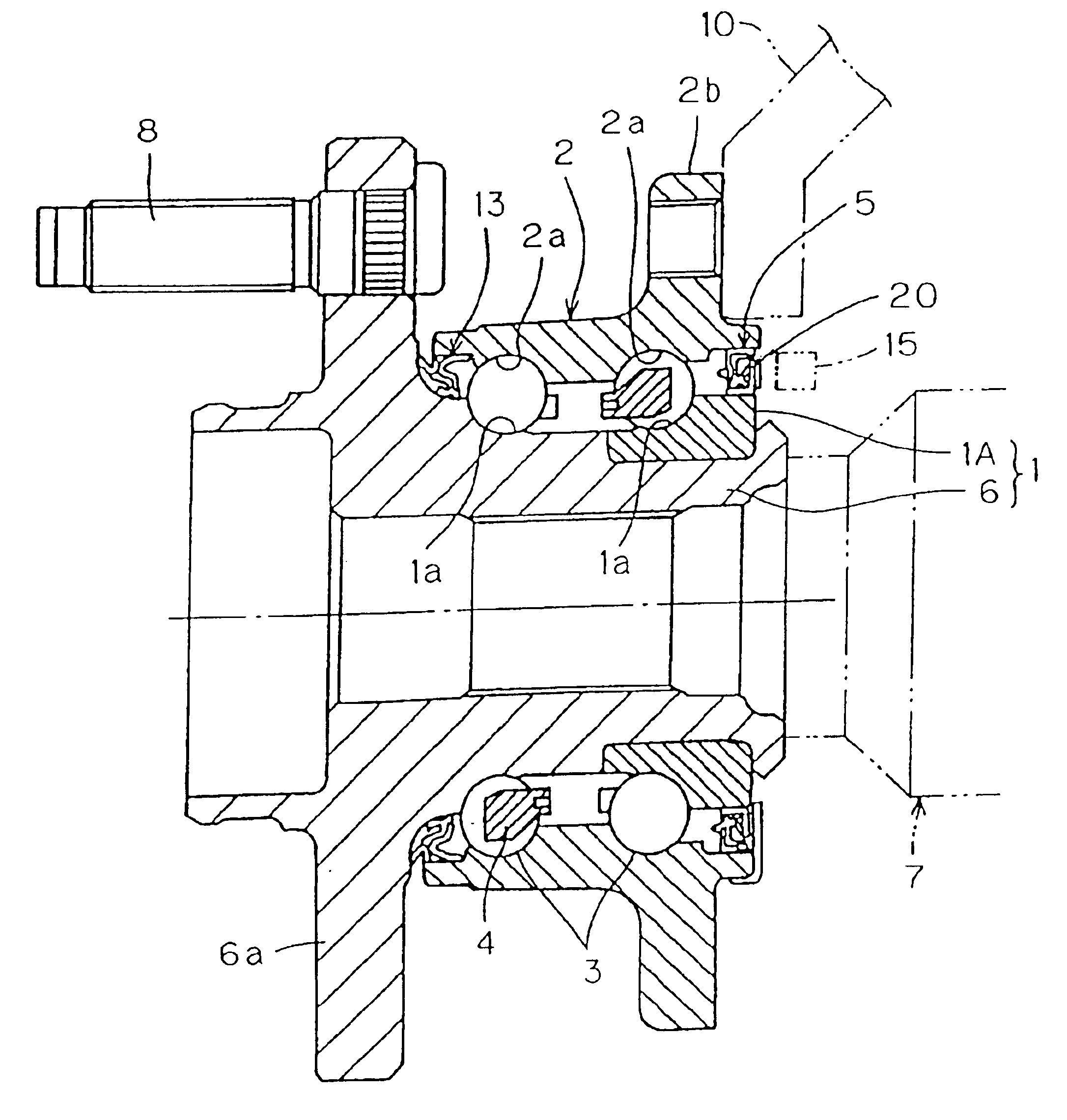
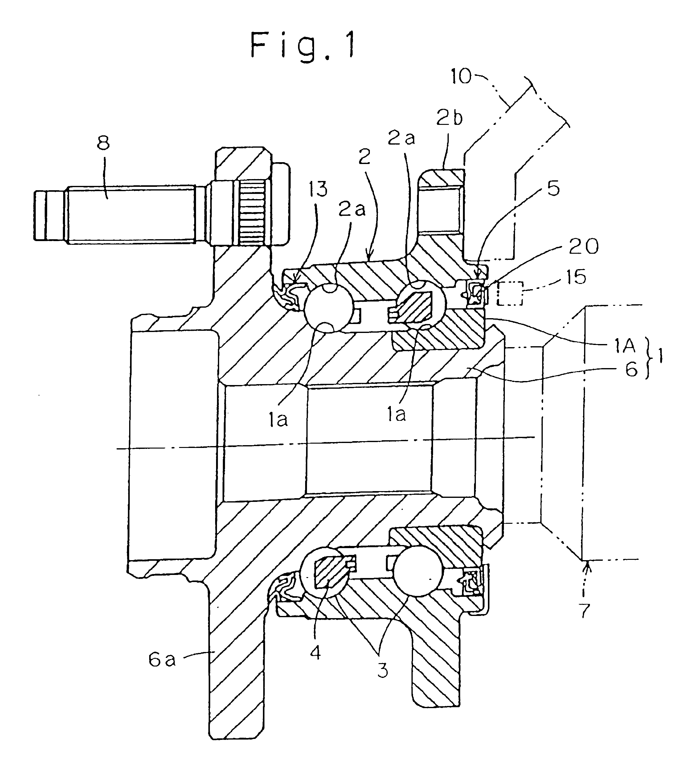
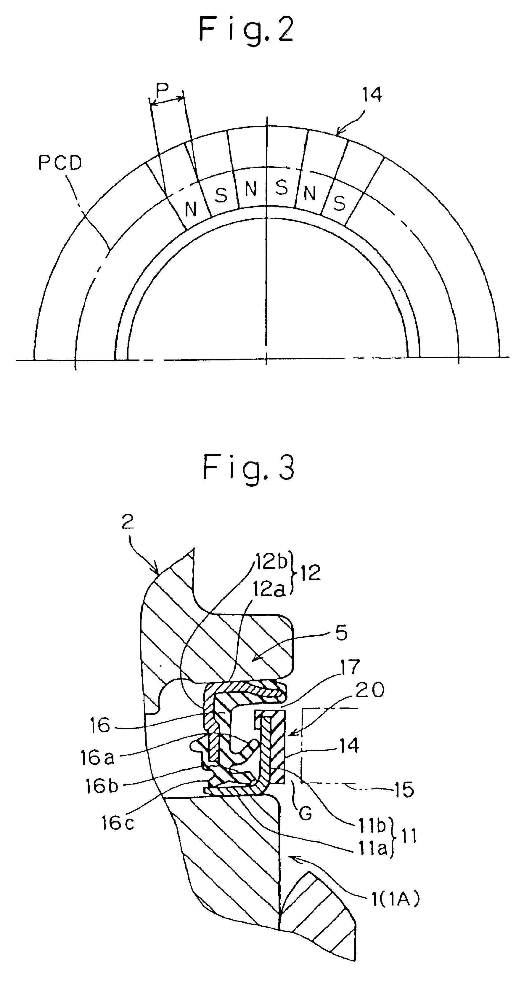
Referring first to FIGS. 1 to 3 pertaining to a first preferred embodiment of the present invention, there is shown, in a longitudinal sectional representation, a wheel bearing assembly equipped with a magnetic encoder. The wheel bearing assembly shown therein includes an inner member 1, an outer member 2 substantially enclosing the inner member 1 to define a generally cylindrical space therebetween, a plurality of rows of rolling elements 3 rollingly movably interposed between the inner and outer members 1 and 2, and axially spaced sealing units 5 and 13 for sealing opposite annular ends of the cylindrical space that is delimited between the inner and outer members 1 and 2. One of the sealing units, that is, the right sealing unit 5 as viewed in FIG. 1 is provided with a magnetic encoder 20 of an axial type as will be detailed hereinafter.

The inner member 1 has an outer peripheral surface formed with axially spaced inner raceways 1a in the form of a radially inwardly recessed groov...


PUM


Abstract

To provide a magnetic encoder in which an air gap between it and a magnetic sensor can be increased and the magnetic force generated thereby can be easily quality-controlled, and a wheel bearing assembly having the magnetic encoder, the magnetic encoder 20 includes a core metal 11 and an elastic member 14 integrated with the core metal 11 in a ring-shaped configuration. The elastic member 14 is made from an elastic material mixed with a powder of magnetic material and has a plurality of different magnetic poles alternating in a direction circumferentially thereof. The elastic member 14 also has a Shore hardness of not lower than Hs 90. A wheel bearing assembly is also provided, which makes use of the magnetic encoder 20 as a component part of a sealing unit 5.

Description

BACKGROUND OF THE INVENTION1. Field of the InventionThe present invention relates to a magnetic encoder forming a part of a rotation detecting device for detecting the rotational speed of a rotary element such as, for example a wheel, and a wheel bearing assembly utilizing such magnetic encoder.2. Description of the Prior ArtA magnetic encoder utilizing a magnetic rubber has hitherto been largely employed in a wheel bearing assembly for supporting a vehicle wheel. This type of magnetic encoder is of a structure in which an elastic member mixed with a powder of magnetic material is integrated with a core metal in a ring-shaped configuration with different magnetic polarities formed alternately in a direction circumferential of the ring-shaped elastic member. This magnetic encoder is, when it is in use, positioned in front of a magnetic sensor with an air gap intervening therebetween, to thereby complete the rotation detecting device for detecting the rotational speed of, for example,...

Claims


Application Information

Patent Timeline
Patent Type & Authority Patents(United States)
IPC IPC(8): B60B27/00F16C33/78F16C33/76F16C19/52F16C19/00G01P3/487G01P3/42G01P3/44G01D5/245B60B35/18F16C19/18F16C41/00
CPCB60B27/00F16C33/78F16C41/007G01P3/443G01P3/487F16C19/186F16C19/185F16C2326/02F16C33/7883
Inventor NORIMATSU, TAKAYUKI
Owner NTN CORP
Why Eureka
Try Eureka