Adjustable reactor with magnetic wedge

A technology for adjusting reactance and magnetic wedge, which is applied in the direction of continuously variable inductor/transformer, transformer/inductor coil/winding/connection, transformer/inductor core, etc. Convenience and other issues, to achieve the effect of simple and convenient adjustment, small vibration, reducing noise and vibration

Inactive Publication Date: 2013-02-20
HARBIN UNIV OF SCI & TECH
View PDF5 Cites 9 Cited by
  • Summary
  • Abstract
  • Description
  • Claims
  • Application Information

AI Technical Summary

Problems solved by technology

[0003] The invention aims to solve the problems of inconvenient adjustment and poor linearity of existing reactors, and provides a magnetic wedge adjustable reactor

Method used


Image

  • Adjustable reactor with magnetic wedge
  • Adjustable reactor with magnetic wedge
  • Adjustable reactor with magnetic wedge

Examples


specific Embodiment approach 1

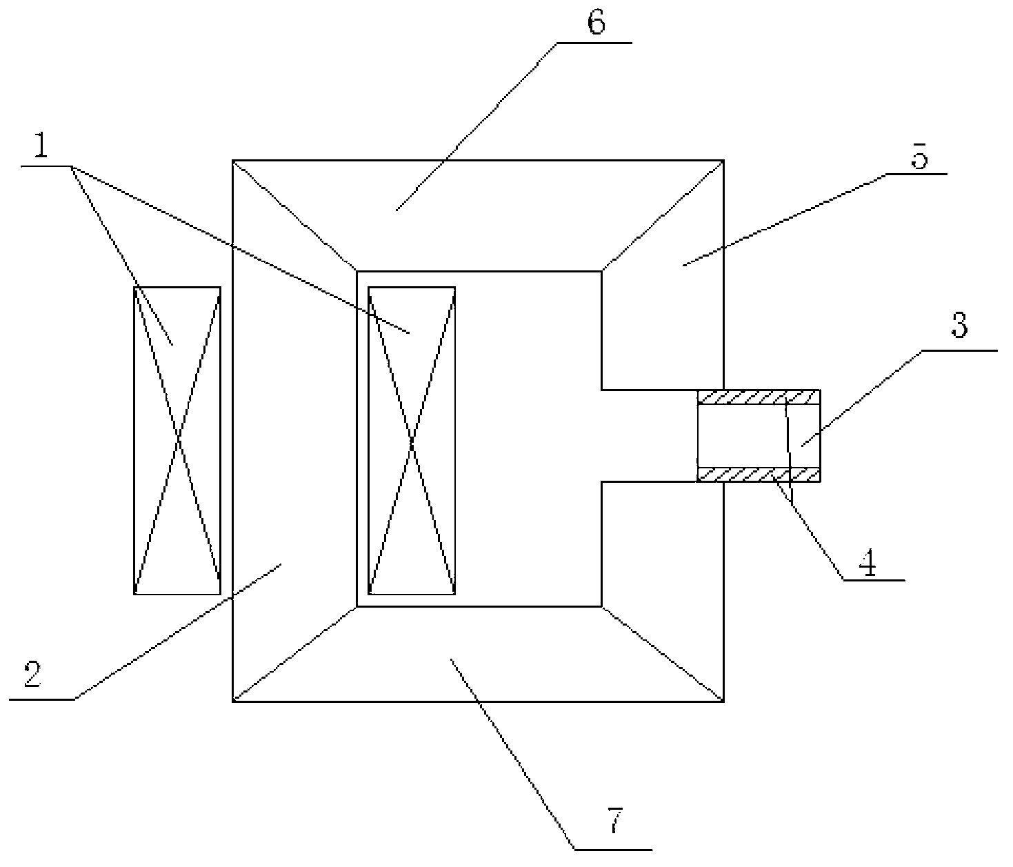
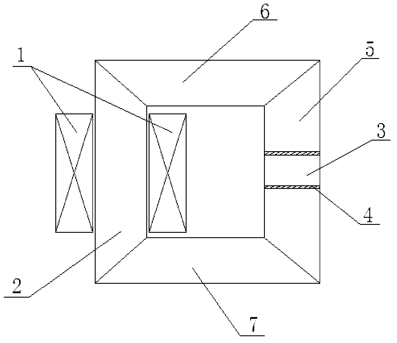
[0024] Specific implementation mode one: the following combination Figure 1 to Figure 8 Describe this embodiment mode. The magnetic wedge type adjustable reactor in this embodiment mode includes a rectangular main magnetic circuit composed of a winding core 2, a lower iron yoke 7, an air gap iron core 5 and an upper iron yoke 6 connected end to end in sequence. frame, which also includes an AC winding 1, a magnetic wedge 3 and two non-ferromagnetic insulating plates 4,

[0025] The lower iron yoke 7 and the upper iron yoke 6 are facing each other in the horizontal direction, and the AC winding 1 is spirally wound on the winding core 2. The center of the air-gapped iron core 5 is a horizontal air gap, and the magnetic wedge 3 is embedded in the horizontal air gap, and the magnetic wedge A non-ferromagnetic insulating plate 4 is arranged between 3 and the two side walls of the horizontal air gap, and the magnetic wedge 3 and two non-ferromagnetic insulating plates 4 are clamped...

specific Embodiment approach 2

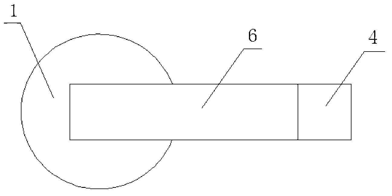
[0039] Specific implementation mode two: the following combination figure 2 This embodiment is described. This embodiment is a further description of Embodiment 1. The horizontal section of the AC winding 1 is circular or rectangular.

[0040] figure 2 The shown AC winding 1 has a circular cross-section, and it can also be wound into a winding with a rectangular cross-section.

specific Embodiment approach 3

[0041] Specific implementation mode three: the following combination Figure 9 and Figure 10 Describe this embodiment, the magnetic wedge type adjustable reactor in this embodiment includes a cylindrical core 8, it also includes an AC winding 1, a magnetic wedge 3 and two non-ferromagnetic insulating plates 4,

[0042] There is an axial air gap on the side wall of the cylindrical iron core 8, and the AC winding 1 is spirally wound on the cylindrical iron core 8. The winding direction of the AC winding 1 is parallel to the axial direction of the cylindrical iron core 8, and the magnetic wedge 3 is embedded In the axial air gap, a non-ferromagnetic insulating plate 4 is arranged between the magnetic wedge 3 and the two side walls of the axial air gap, the magnetic wedge 3 and two non-ferromagnetic insulating plates 4 Clamped in the axial air gap.

[0043] Figure 9 As shown, the magnetic circuit adopts a cylindrical iron core 8 structure, and the AC winding 1 is spirally wou...


PUM


Abstract

The invention relates to an adjustable reactor with a magnetic wedge, which belongs to the technical field of adjustable reactor manufacturing and aims to solve the problems that the conventional reactor is inconvenient to adjust and poor in linearity. The adjustable reactor comprises a rectangular main magnetic circuit frame, an alternating current winding, the magnetic wedge and two nonferromagnetic insulating plates, wherein the rectangular main magnetic circuit frame is composed of a winding iron core, a lower iron yoke, an iron core with an air gap and an upper iron yoke which are sequentially connected with one another end to end; the lower iron yoke and the upper iron yoke are opposite in the horizontal direction; the alternating current winding spirally wraps the winding iron core; the horizontal air gap is formed in the center of the iron core; the magnetic wedge is embedded in the horizontal air gap; the nonferromagnetic insulating plates are respectively arranged between the magnetic wedge and the two side walls of the horizontal air gap; and the magnetic wedge and the two nonferromagnetic insulating plates are clamped and fixed in the horizontal air gap. The technical scheme of the adjustable reactor disclosed by the invention can be applied to manufacturing of reactors.

Description

technical field [0001] The invention relates to a magnetic wedge type adjustable reactor, which belongs to the technical field of adjustable reactor production. Background technique [0002] At present, the structures of known reactors whose inductance is adjusted by adjusting the air gap are all composed of an AC winding, an air gap, a moving iron core and a fixed iron core. The moving iron core and the fixed iron core are symmetrically distributed on the upper and lower sides of the air gap respectively. Moving the moving iron core vertically can increase or decrease the height of the air gap, change the equivalent reluctance in the magnetic circuit, and then change the inductance of the reactor. But it has the following disadvantages: 1. Since the moving direction of the moving iron core is parallel to the direction of the magnetic flux, a large electromagnetic force will be generated between the moving iron core and the fixed iron core when the air gap is adjusted, causi...

Claims


Application Information

Patent Timeline
Patent Type & Authority Applications(China)
IPC IPC(8): H01F21/02H01F27/24H01F27/30
Inventor 魏新劳官瑞杨王永红聂洪研
Owner HARBIN UNIV OF SCI & TECH
Why Eureka
Try Eureka