Synchronous reluctance motor and underwater pump

A synchronous reluctance and motor technology, applied in pumps, magnetic circuits, pump devices, etc., can solve problems such as efficiency and power factor loss

Inactive Publication Date: 2015-01-14
KSB AG
View PDF5 Cites 7 Cited by
  • Summary
  • Abstract
  • Description
  • Claims
  • Application Information

AI Technical Summary

Problems solved by technology

However, in the case of submerged motors the use of synchronous reluctance motors in the field of submerged pumps is currently only possible with significant losses in terms of efficiency and power factor due to the motor construction due to the application

Method used


Image

  • Synchronous reluctance motor and underwater pump
  • Synchronous reluctance motor and underwater pump
  • Synchronous reluctance motor and underwater pump

Examples


Embodiment Construction

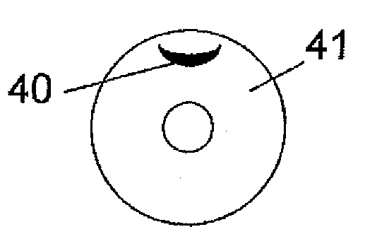
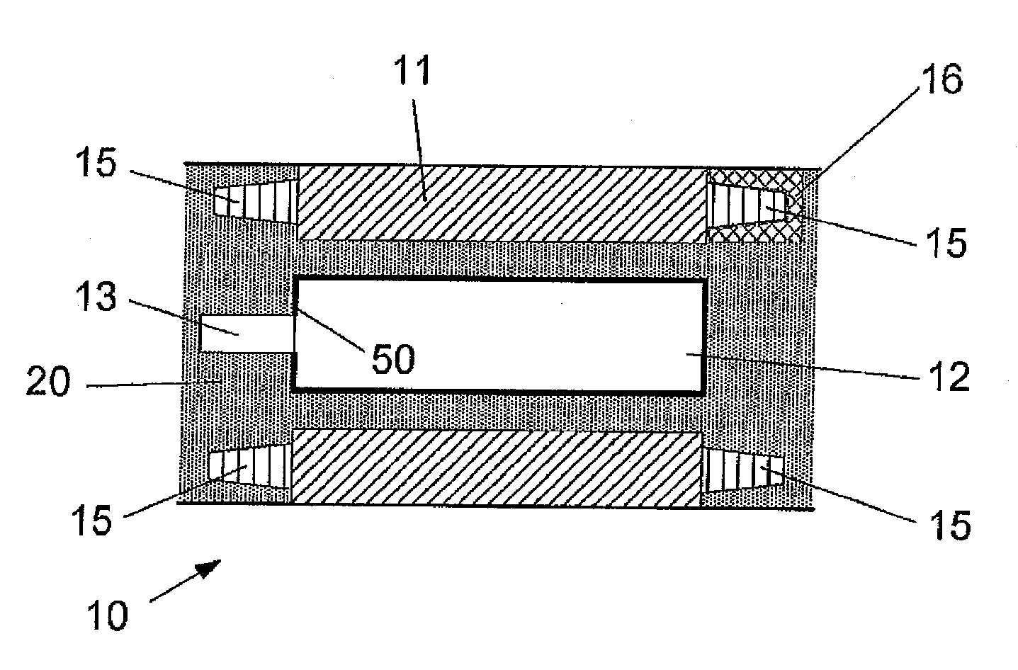
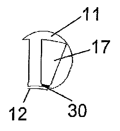
[0037] figure 1The synchronous reluctance motor 10 shown in FIG. 2 has a conventional stator 11 and a rotor 12 mounted rotatably relative to the stator 11 , which itself is arranged coaxially on a shaft 13 . The rotor body consists of laminated laminations (Paket), for example a plate pack (Blechpaket), wherein the individual layers or plates are stacked in the axial direction of the shaft 13 . From figure 2 A schematic representation of a single layer can be derived.

[0038] The distance between the rotor wall and the stator wall is called the air gap. According to the present invention in figure 1 The middle motor inner chamber is filled with a ferrofluid 20 , whereby the magnetic permeability in the region between the stator 11 and the rotor 12 is increased and the relatively large geometric distance is compensated. The interaction between the rotor 12 and the stator 11 (ie the reluctance resistance) will increase due to the increased magnetic permeability.

[0039] ...


PUM


Abstract

The present invention relates to a synchronous reluctance motor for an underwater pump having a stator and a rotor which comprises a fluid barrier section for forming one or more magnetic pole pairs, wherein the airgap between the rotor (12) and the stator (11) is at least partially filled with a ferrofluid (20). A further partial aspect of the invention relates to an underwater pump with such a synchronous reluctance motor for driving the pump.

Description

technical field [0001] The invention relates to a synchronous reluctance motor for driving a submerged pump with a stator-rotor arrangement, wherein the rotor includes flux barrier cutouts for shaping one or more magnetic pole pairs. Furthermore, the invention relates to a submerged pump with such a drive motor. Background technique [0002] Submersible motor pumps are used to transport liquid media in boreholes. The outside of the housing of the motor is completely or partially wetted by the conveyed medium, usually ground water. The pump drive motor used is encapsulated in order to prevent the delivery medium from penetrating into the motor interior. [0003] The motor chamber is filled with a suitable liquid medium, preferably a water-glycol mixture or oil, which both wets the unprotected rotor and, if the stator is unprotected, seals the stator together with the plastic insulated winding wires Moisten together or with the stator protected the sealing housing (Spaltroh...

Claims


Application Information

Patent Timeline
Patent Type & Authority Applications(China)
IPC IPC(8): H02K5/12H02K5/132H02K5/167H02K7/09
CPCH02K2201/03H02K5/12H02K5/132H02K2213/03H02K5/1677H02K7/09H02K1/02H02K1/06H02K1/22H02K3/42F04D13/08
Inventor S.乌尔舍尔
Owner KSB AG
Why Eureka
Try Eureka