
Adjustable mid air gap magnetic latching solenoid

a magnetic latching solenoid and air gap technology, applied in the field of magnet latching solenoids, can solve the problems of inability to meet customer requirements, non-uniform piston action, deleterious smallest air gap, etc., to achieve the effect of increasing the magnetic efficiency of the solenoid, improving the performance of the solenoid, and increasing the magnetic latching for

Inactive Publication Date: 2012-01-31
SAIA BURS
View PDF15 Cites 8 Cited by
  • Summary
  • Abstract
  • Description
  • Claims
  • Application Information

AI Technical Summary

Benefits of technology

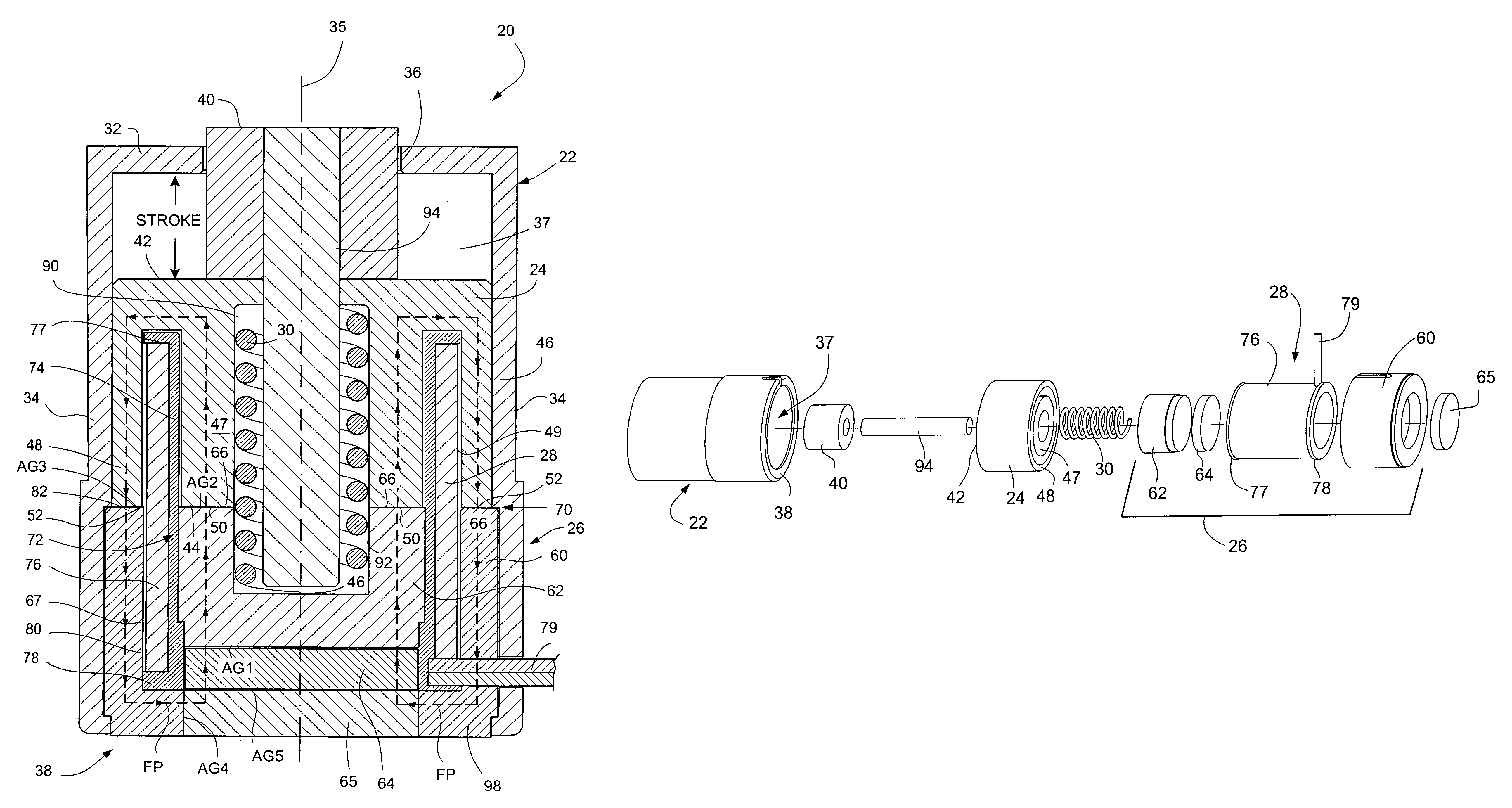
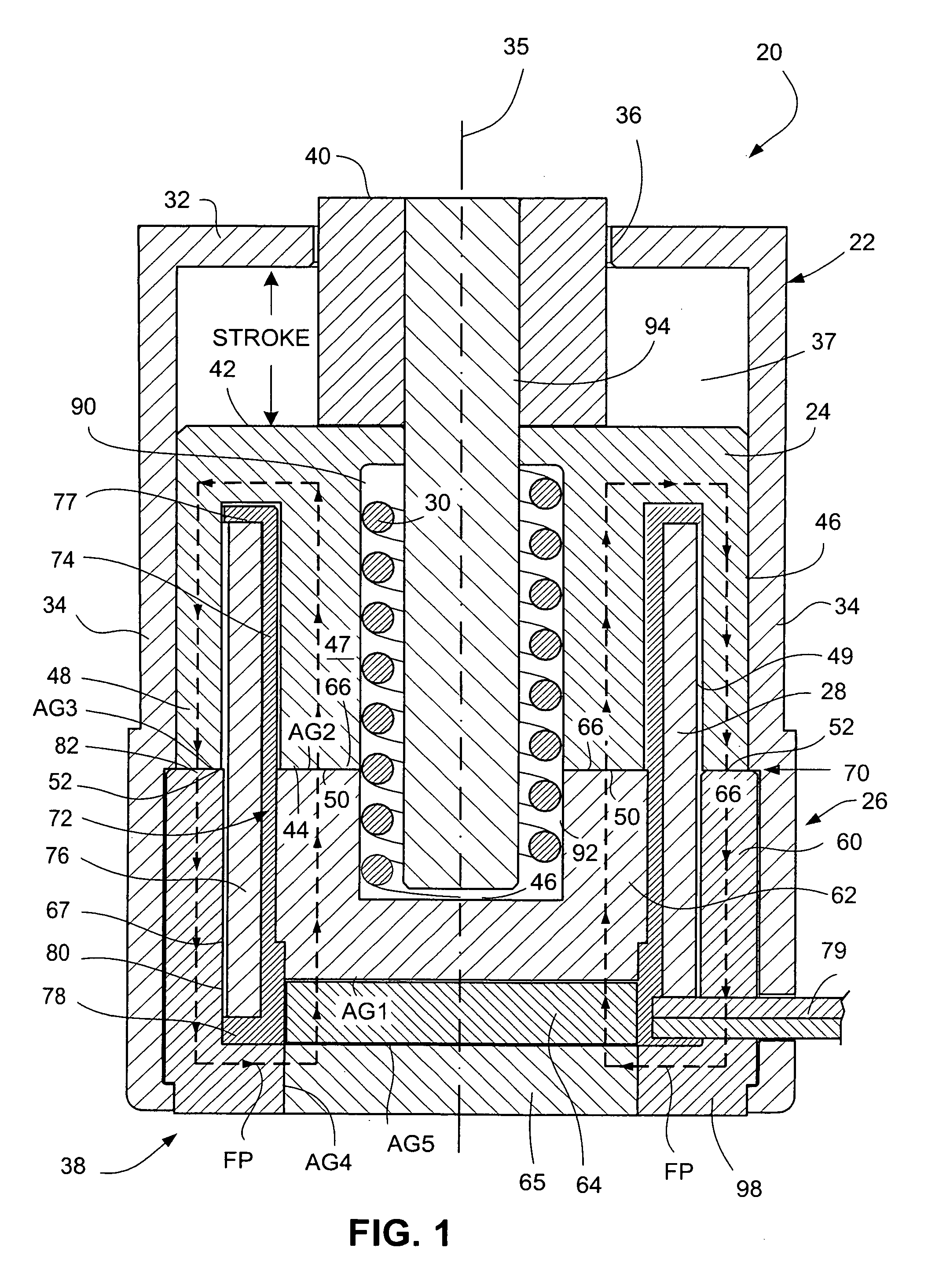
[0036]This technology therefore provides an approach that combines both a “zero” air gap and mid air gap design to maximize the solenoid's magnetic efficiency while also providing a more consistent magnetic circuit when the metal components latch for improved solenoid performance, i.e. a higher magnetic latching force.
[0037]The technology provides, e.g.: 1) a more efficient magnetic circuit to increase the magnetic latching force; 2) a design that virtually eliminates all air gaps by employing an adjustable pole piece; and, 3) a robust, low-cost and easily assembled design with flexibility for various power levels, mounting schemes and output adaptors.

Problems solved by technology

As the moving metal component is re-latched to its mating stationary metal component during repeated actuations, variations in the magnetic circuit and air gaps between the metal components of typical magnetic latching solenoids result in release power variations that are unacceptable to the customer.
The release power variations can result in piston action that is non-uniform (e.g., with respect to one or more of piston position / placement, piston actuation power, or piston speed / response).
Even the smallest air gap is deleterious to the electromagnetic flux fields and flux paths which travel through the stationary member and the moveable member.

Method used


Image

  • Adjustable mid air gap magnetic latching solenoid
  • Adjustable mid air gap magnetic latching solenoid
  • Adjustable mid air gap magnetic latching solenoid

Examples


Embodiment Construction

[0052]In the following description, for purposes of explanation and not limitation, specific details are set forth such as particular architectures, interfaces, techniques, etc. in order to provide a thorough understanding of the present invention. However, it will be apparent to those skilled in the art that the present invention may be practiced in other embodiments that depart from these specific details. That is, those skilled in the art will be able to devise various arrangements which, although not explicitly described or shown herein, embody the principles of the invention and are included within its spirit and scope. In some instances, detailed descriptions of well-known devices, circuits, and methods are omitted so as not to obscure the description of the present invention with unnecessary detail. All statements herein reciting principles, aspects, and embodiments of the invention, as well as specific examples thereof, are intended to encompass both structural and functiona...


PUM

PropertyMeasurementUnit
magnetically permeableaaaaaaaaaa
permanent magnetic flux fieldaaaaaaaaaa
permanent magnetic fluxaaaaaaaaaa

Abstract

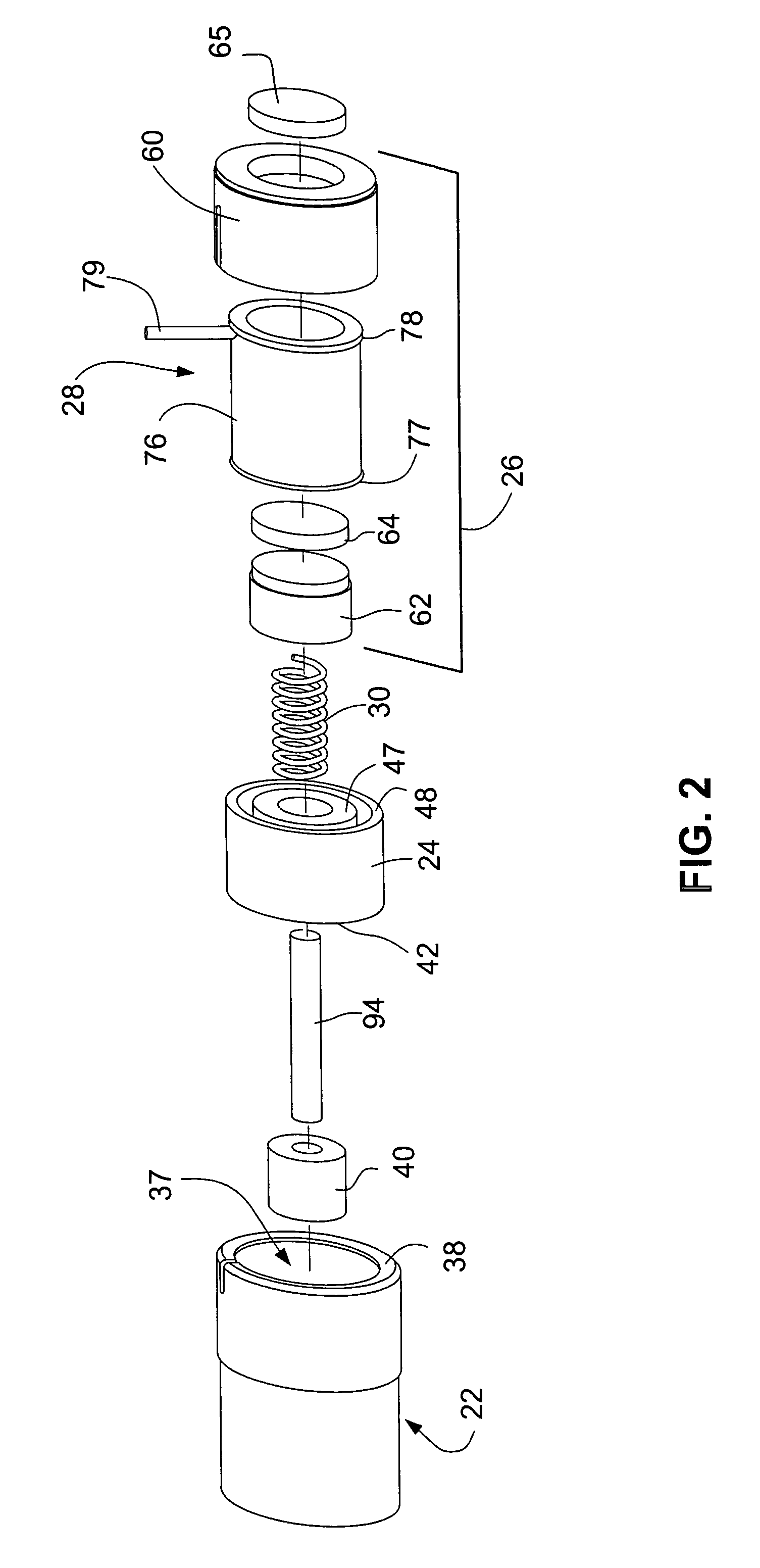
A magnetic latching solenoid comprises a housing, a moveable magnetically permeable member, a stationary magnetic assembly, a counter flux generator; and, a spring. A substantially equal extent of the moveable magnetically permeable member and stationary magnetic assembly along results in an air gap interface being essentially mid-way between the opposite axial extremities of the moveable magnetically permeable member and stationary magnetic assembly, thereby enhancing an attracting force of a permanent magnet that comprises the stationary magnetic assembly. In an example embodiment, the stationary magnetic assembly comprises a pole member which is adjustably positionable to minimize air gaps.

Description

[0001]This application claims the priority and benefit of U.S. Provisional Patent Application 60 / 907,972, filed Apr. 25, 2007, entitled “ADJUSTABLE MID AIR GAP MAGNETIC LATCHING SOLENOID”; and U.S. Provisional Patent Application 60 / 996,888, filed Dec. 10, 2007, entitled “ADJUSTABLE MID AIR GAP MAGNETIC LATCHING SOLENOID”; both of which are incorporated herein by reference in their entirety.BACKGROUND[0002]I. Technical Field[0003]This invention pertains to the field of solenoids, and particularly to magnetic latching solenoids.[0004]II. Related Art and Other Considerations[0005]A typical solenoid has a moveable member which is connected to or integral with a plunger or piston. The moveable piston or plunger, which can be in the form of an output shaft, is the serving or working element / aspect of the solenoid that can be employed in any of various applications or utilizations.[0006]One type of solenoid is a “power stroking” or “power on” solenoid. In a natural state of a power strokin...

Claims


Application Information

Patent Timeline
Patent Type & Authority Patents(United States)
IPC IPC(8): H01F7/00H01F7/08
CPCH01F7/122H01F7/127H01F7/1615H01F2007/1669Y10T29/49105Y10T29/49075
Inventor GRUDEN, JAMES M.
Owner SAIA BURS
Learn More