Cup attaching apparatus

a technology for attaching apparatuses and cups, which is applied in the direction of optical surface grinding machines, manufacturing tools, diagnostic recording/measuring, etc., can solve the problems of affecting the accuracy of positioning accuracy of attaching cups, and the likelihood of the support pin dropping off the support pin, etc., to achieve accuracy and efficiency

Active Publication Date: 2007-10-04
NIDEK CO LTD
View PDF6 Cites 9 Cited by
  • Summary
  • Abstract
  • Description
  • Claims
  • Application Information

AI Technical Summary

Benefits of technology

[0008]The present invention has been made in view of the above circumstances and has an object to provide a cup attaching apparatus capable of attaching a cup to a lens with accuracy and efficiency.

Problems solved by technology

Meanwhile, in the case where the cup is to be attached to the lens having the rear refractive surface different in shape from the front refractive surface, such as a prism lens and an astigmatic lens (a toric lens), the following problem may arise.
When the rear refractive surface of the lens is supported by the support pins fixed with the supporting plane being held in the horizontal position, the front refractive surface of the lens tends to incline, which is likely to cause errors in positioning accuracy in attaching the cup.
However, if the supporting plane is allowed to incline by the vertical movement of the support pins, the supported lens is likely to drop off the support pins unless the lens is pressed from above.

Method used


Image

  • Cup attaching apparatus
  • Cup attaching apparatus
  • Cup attaching apparatus

Examples


Embodiment Construction

[0033]A detailed description of a preferred embodiment of the present invention will now be given referring to the accompanying drawings.

[0034]

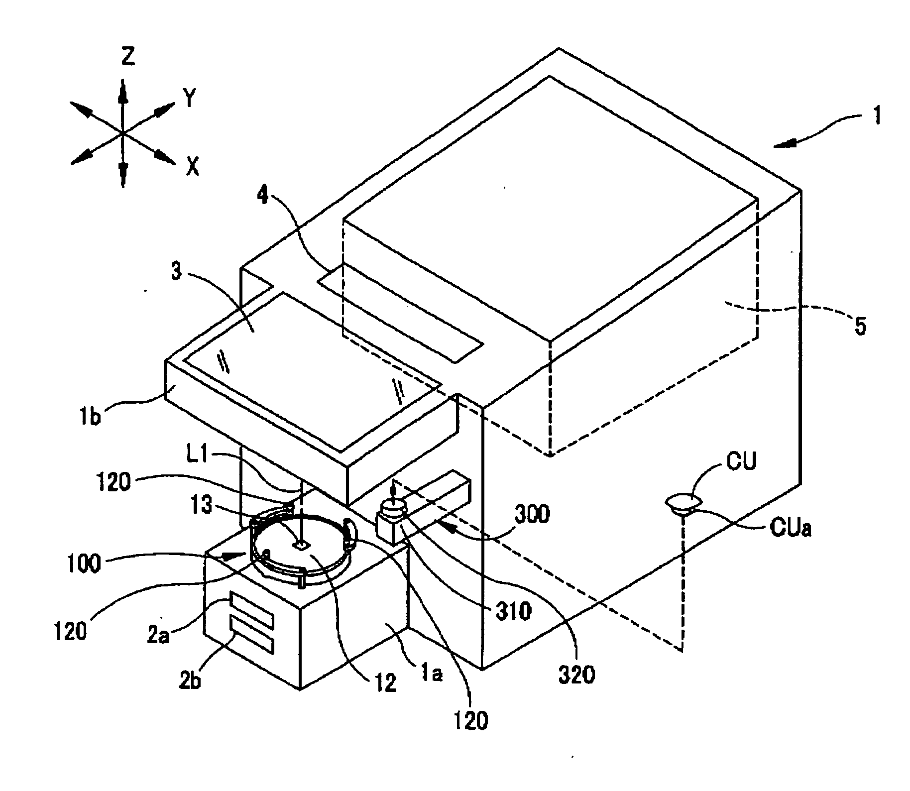
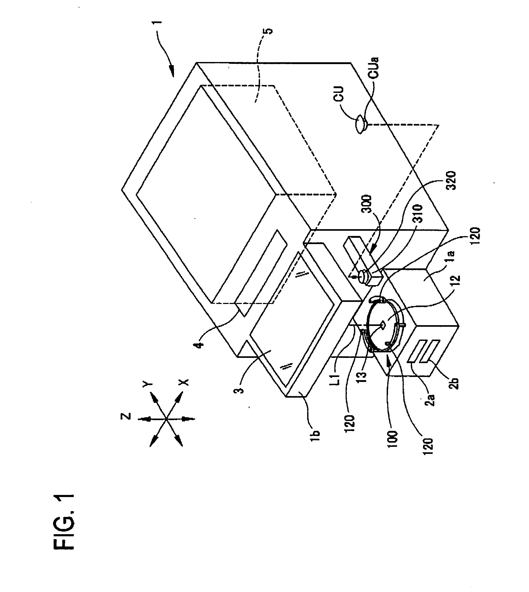
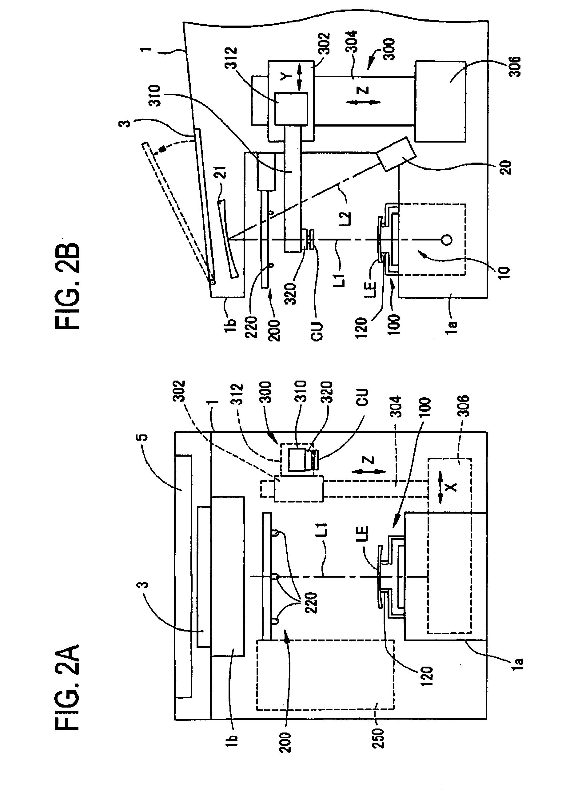
[0035]FIG. 1 is a schematic perspective view of a cup attaching apparatus 1 of the present embodiment. FIGS. 2A and 2B are schematic configuration views of the attaching apparatus 1; FIG. 2A is a front view and FIG. 2B is a side view.

[0036]In an upper portion of the attaching apparatus 1, an eyeglass frame measuring device 5 is placed (built) and a switch panel (an input part) 4 for the measuring device 5 is placed. In an upper front portion of the attaching apparatus 1, forming a canopy part 1b, a display (a display and input part) 3 of a touch screen type is placed. The display 3 is movable to change the orientation of a screen according to the posture of an operator or the like (see FIG. 2B). On a lower front portion of the attaching apparatus 1 forming a base part 1a, a lens mount (a lens support) 100 having three support pins 120 is plac...


PUM

PropertyMeasurementUnit
diameteraaaaaaaaaa
diameteraaaaaaaaaa
diameteraaaaaaaaaa

Abstract

A cup attaching apparatus for attaching a cup to an eyeglass lens, comprises: a lens mount on which the lens is to be mounted; at least three support pins provided on the lens mount to support the lens when a rear refractive surface of the lens is brought in contact with the support pins; a holding unit adapted to hold the support pins so that a supporting plane defined by the support pins is inclineable; a lens clamp for clamping the lens in cooperation with the lens mount when the lens is mounted on the lens mount; at least three presser pins provided on the lens clamp to clamp the lens when a front refractive surface of the lens is brought in contact with the presser pins; and a locking unit adapted to keep the supporting plane defined by the support pins in a substantially horizontal position when the lens is not clamped between the lens mount and the lens clamp.

Description

BACKGROUND OF THE INVENTION[0001]1. Field of the Invention[0002]The present invention relates to a cup attaching apparatus for attaching a cup, used for fixing an eyeglass lens to an eyeglass lens processing apparatus, to the lens.[0003]2. Description of Related Art[0004]There is a cup attaching apparatus called a blocker for attaching a cup, used for fixing an eyeglass lens to an eyeglass lens processing apparatus, to the lens. This cup attaching apparatus comprises a blocking arm provided with a cup holder in the vicinity of a distal end of the arm, the holder being used to hold the cup, and a lens mount (a lens support) on which the lens is to be mounted. When the lens is mounted on the mount, the cup is mounted (fitted) in the holder, and the arm is moved downward, the cup is attached to a front refractive surface of the lens.[0005]Such attaching apparatus is commonly arranged to support a rear refractive surface of the lens with at least three support pins fixedly provided on t...

Claims


Application Information

Patent Timeline
Patent Type & Authority Applications(United States)
IPC IPC(8): B24B51/00
CPCA61B5/0408B24B13/0055A61B5/0468A61B5/0464A61B5/25A61B5/364A61B5/363B24B13/00B24B13/005
Inventor MATSUYAMA, YOSHINORI
Owner NIDEK CO LTD
Why Eureka
Try Eureka