Process for making UHF antennas for EAS and RFID tags and antennas made thereby

a technology of uhf antennas and antennas, which is applied in the field of making uhf antennas, can solve the problems of not being the most cost-effective method for producing very thin uhf antennas, and the techniques of u.s. pat. no. 6,988,666

Active Publication Date: 2007-10-11
CHECKPOINT SYST INC
View PDF26 Cites 12 Cited by
  • Summary
  • Abstract
  • Description
  • Claims
  • Application Information

AI Technical Summary

Problems solved by technology

Accordingly, the techniques of U.S. Pat. No. 6,988,666 (Appalucci et al.) may not be the most cost effective methods for the production of very thin UHF antennas.

Method used


Image

  • Process for making UHF antennas for EAS and RFID tags and antennas made thereby
  • Process for making UHF antennas for EAS and RFID tags and antennas made thereby
  • Process for making UHF antennas for EAS and RFID tags and antennas made thereby

Examples


Embodiment Construction

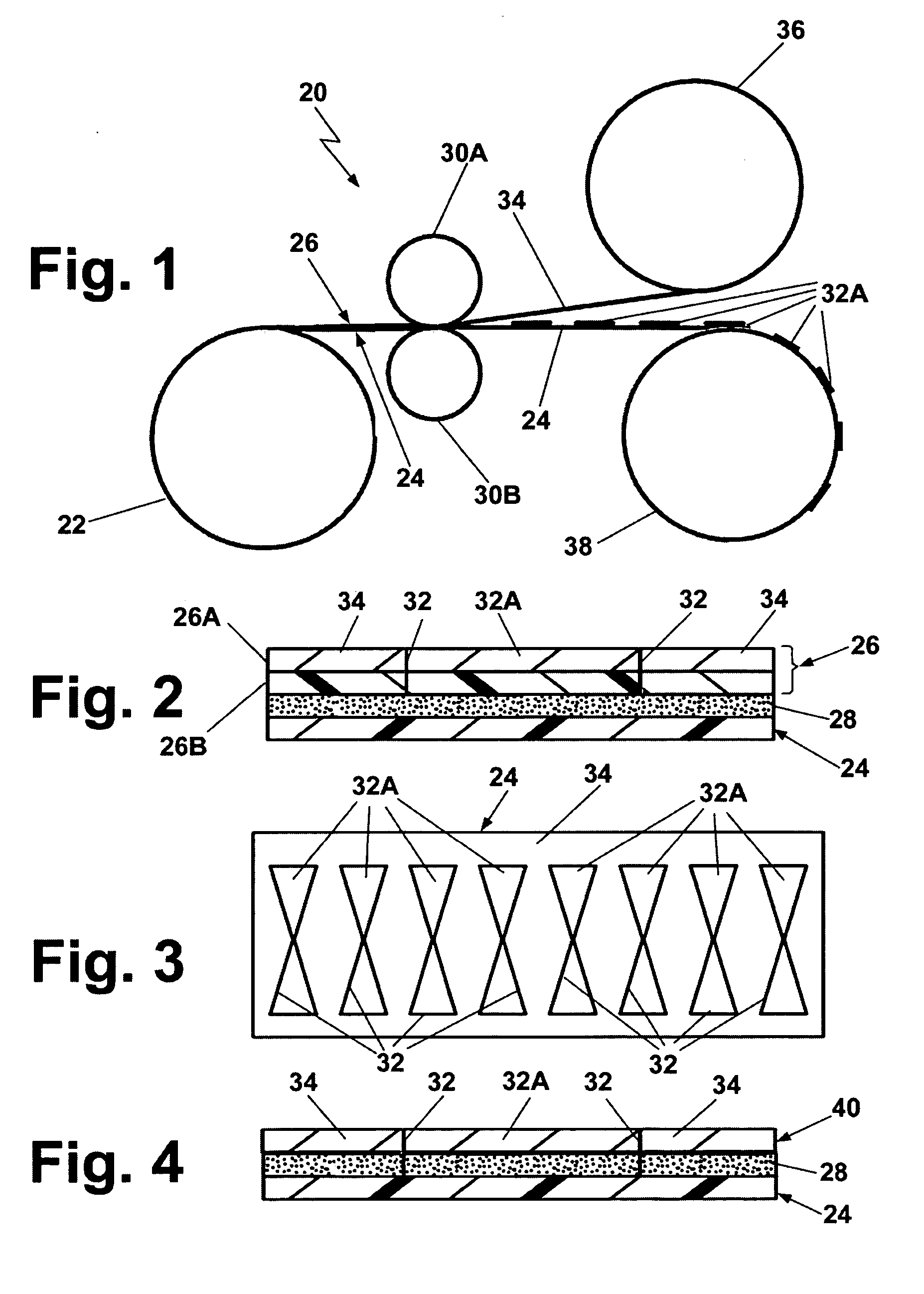
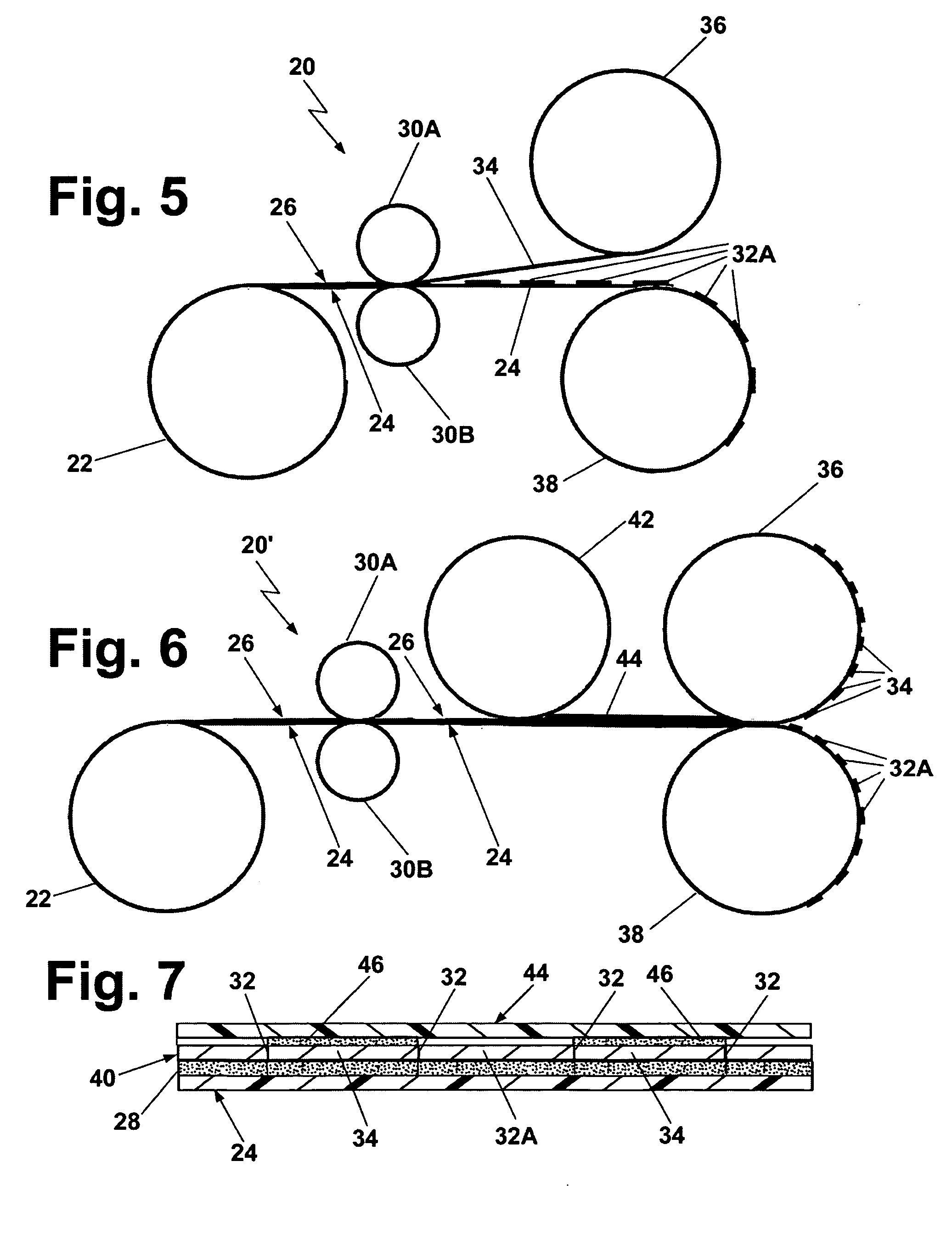
[0024] Referring now to the various figures of the drawings wherein like reference characters refer to like parts there is shown at 20 in FIG. 1 a system 20 for carrying out one exemplary method of this invention to produce a series of UHF antennas in a very expeditious manner and at a very low cost. As will be appreciated by those skilled in the art from the description to follow, those advantages stem at least partially from the fact that the methods of this invention can be accomplished using standard installed equipment that has been available for several decades in the label converting industry, but modified as will be described below to fabricate UHF antennas.

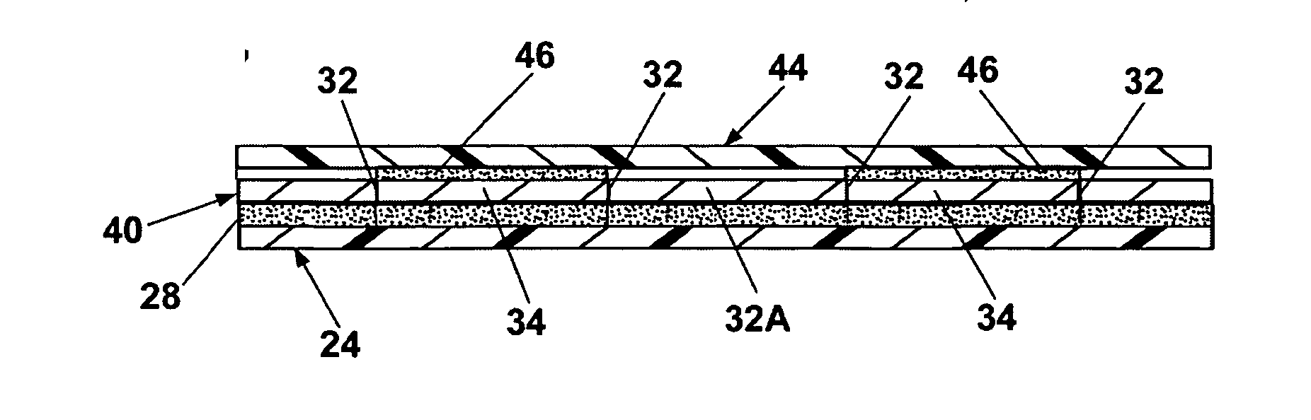
[0025] The exemplary system 20 of FIG. 1 basically comprises a reel 22 containing a flexible liner or carrier web 24 (FIGS. 1 and 2) and a flexible conductive laminate web 26 (FIGS. 1 and 2) releasably secured to the carrier web by a layer of any suitable adhesive 28 (FIG. 2), e.g., hot melt, or water based systems, usin...


PUM

PropertyMeasurementUnit
thicknessaaaaaaaaaa
thicknessaaaaaaaaaa
frequencyaaaaaaaaaa

Abstract

A method of making UHF antennas for security tag and antennas thereby. A web of electrically conductive material having a thickness in the range of approximately 5 to approximately 50 microns is releasably secured to a carrier web using a releasably securable adhesive substantially coextensive with the conductive web. A series of antennas of a desired shape are die-cut into the conductive web, but not into the carrier web. The portion of the conductive web not making up the antennas is in the form of scrap and is removed, thereby leaving the series of antennas releasably secured to the carrier sheet. The antennas are arranged to be removed from the carrier sheet, whereupon the releasably securable adhesive is transferred to them, so that they may be subsequently secured to other components to form a security tag.

Description

BACKGROUND OF THE INVENTION [0001] 1. Field of Invention [0002] The current invention relates to EAS and RFID security tags and more particularly to methods of making UHF antennas for such tags and antennas made thereby. [0003] 2. Description of Related Art [0004] RFID tags may be either active or passive. Active tags include their own on-board power, whereas passive use radio frequency signals from a transmitter to power the tag. When a passive tag receives the signal from the incident electromagnetic field, its antenna absorbs the energy received and directs it to an integrated circuit forming a part of the tag. The incident electromagnetic may contain data or instructions encoded into the signal. Using a portion of the energy received, the integrated circuit can then communicate back to a reader the details of data stored in the integrated circuit's on-board memory. The distance at which an RFID tag can be read / write depends on the output power of the RFID reader, the surrounding...

Claims


Application Information

Patent Timeline
Patent Type & Authority Applications(United States)
IPC IPC(8): H01P11/00
CPCB32B37/12B32B38/10B32B2519/02Y10T29/49002Y10T29/49018Y10T29/49016H01Q1/2225
Inventor COTE, ANDREDUSCHEK, DETLEF
Owner CHECKPOINT SYST INC
Why Eureka
Try Eureka