
Cable guide support for cable-guided tank gauge

a technology of cable guide and tank gauge, which is applied in the direction of engine lubrication, liquid/fluent solid measurement, portability lifting, etc., can solve the problems of cable losing contact or slipping off the pulley, unreliable operation of the tank gauge, and increasing wear and slack in the cable. , to achieve the effect of reducing debris and foreign materials

Inactive Publication Date: 2007-10-11
TITAN LOGIX
View PDF8 Cites 6 Cited by
  • Summary
  • Abstract
  • Description
  • Claims
  • Application Information

AI Technical Summary

Benefits of technology

[0015] the cable-engaging element is substantially wider than the openings to prevent the cable from coming off the cable-engaging element and minimizes jamming;
[0017] the cable-engaging element is enclosed to reduce debris and foreign materials from interfering with performance of the cable guide support.

Problems solved by technology

There have been problems with this type of design of the pulley for guiding the cable.
In particular, the cable has a tendency to rub against the sides of the pulley causing increased wear and slack in the cable over time.
This can result in the cable losing contact or slipping off of the pulley.
This can cause unreliable operation of the tank gauge since the cable can impinge on the sides of the pulley, or even get jammed between the pulley and the pulley support.
Furthermore, one of the pulleys is exposed to outside environmental conditions that can affect the performance of the tank gauge.
Dirt, debris, snow or ice on the cable, as a result of being exposed to the environment, can cause jamming or impair operability of the tank gauge.
The design of the pulley for the tank gauge of this patent is similar to that of Barritt and therefore suffers from the same drawbacks as mentioned above.
In particular, the tank gauge provided by Grimes necessitates the use of a tensioner as reduced tension in the cable greatly increases risk of the cable losing contact or disengaging from the pulley.
Also, the pulley is not enclosed and is exposed to the outside, which is a concern since the tank gauge is needed to operate year round.

Method used


Image

  • Cable guide support for cable-guided tank gauge
  • Cable guide support for cable-guided tank gauge
  • Cable guide support for cable-guided tank gauge

Examples


Embodiment Construction

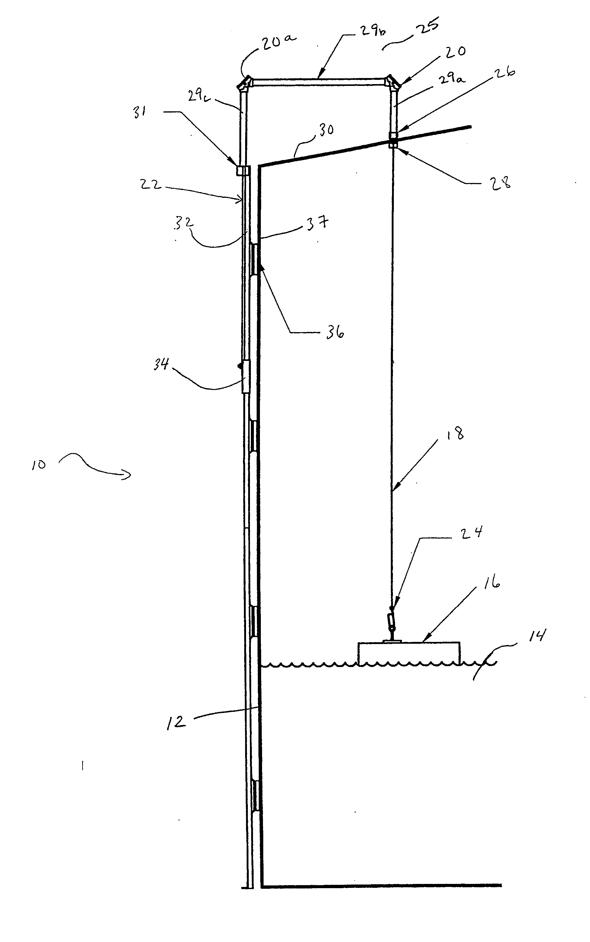
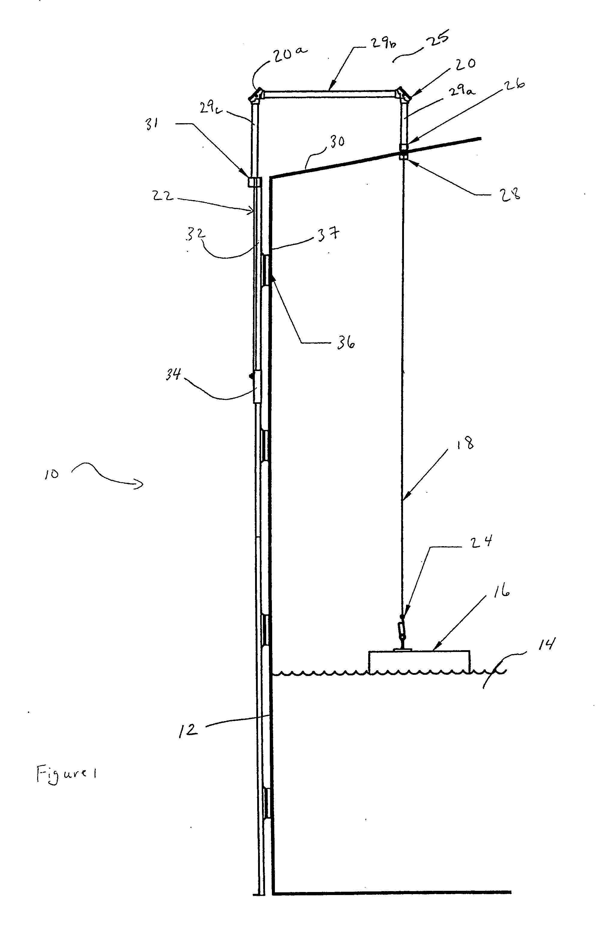
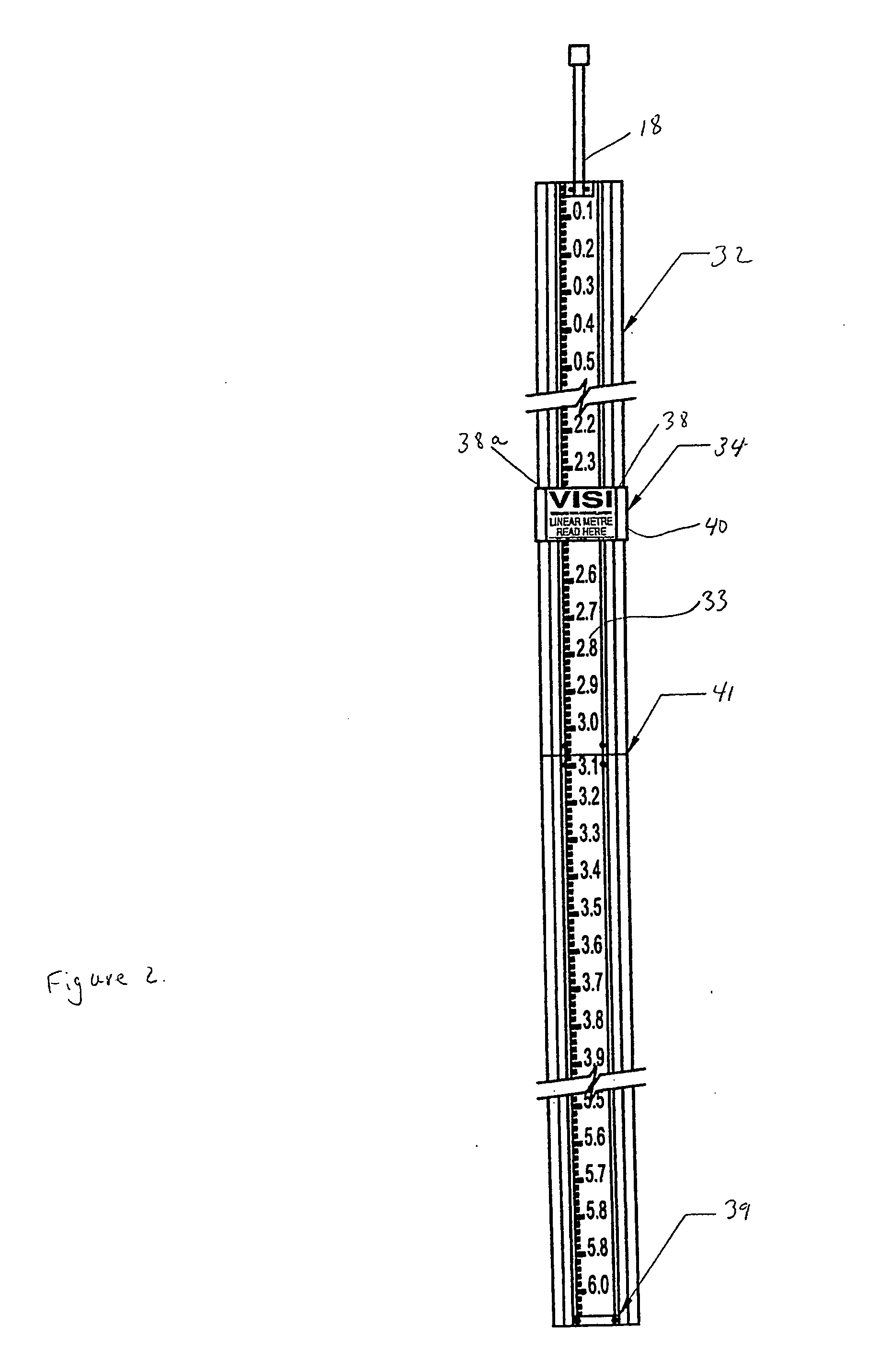
[0025]FIG. 1 illustrates an embodiment of a tank gauge system 10 mounted on tank 12 that contains liquid 14, such as oil, drilling mud, petroleum, water, chemicals or the like. Tank gauge system 10 comprises a float member 16, a cable 18, a cable guide support 20 and an indicator mechanism 22. Float member 16 has a predetermined weight and buoyancy so as to float in liquid 14. Float member 16 follows the change in the level of liquid 14 in tank 12. Design, configuration and material used in construction of float member 16 are known to those skilled in the art. Materials such as corrosive resistant plastics, PVC and metals having particular desirable properties that are resistant to the nature of the liquid 14 can be used.

[0026] In a representative embodiment, float member 16 is connected to cable 18, which can be made of stainless steel, through clip 24 that enables float member 16 to be detached, when desired. Other types of connectors, known to those skilled in the art, for conne...


PUM


Abstract

A tank gauge system is provided in one embodiment comprising a float, a cable, an indicator and at least one cable guide support. The float is in a tank containing liquid and moves with it. The cable connects the float to the indicator on the outside through the cable support for communicating the liquid level in the tank. The cable support comprises a body having two side openings merging into a cavity formed on a top portion of the body. A roller is positioned in the cavity, between the two openings and is rotatable about an axis transverse to the direction of cable movement. The roller has a predetermined axial length that is substantially wider than each of the openings so that the cable moving through the openings is urged to maintain contact with the roller. This prevents the cable from coming off the roller and minimizes jamming.

Description

RELATED APPLICATION [0001] The present application claims priority under 35 U.S.C. §119 of Canadian Patent Application 2,532,849 filed Jan. 13, 2006, the entire disclosure of which is considered as part of the disclosure of the present application and is hereby incorporated by reference herein. FIELD OF THE INVENTION [0002] The present invention relates to the field of cable guide supports. More particularly, the present invention relates to the field of cable-guide supports for use in cable-guided mechanical tank gauge systems. BACKGROUND [0003] A storage vessel in the form of a tank is commonly used, particularly in the oil and gas industry, for containing liquids and gases. The tank may be equipped with a measuring instrument for determining the amount of liquid in the tank. [0004] The measuring instrument often employed for determining liquid levels in the tank is a mechanical tank gauge. A float is contained in the tank and floats on the liquid. The float is attached to one end...

Claims


Application Information

Patent Timeline
Patent Type & Authority Applications(United States)
IPC IPC(8): G01F23/30
CPCG01F23/42
Inventor MCGILLIS, GREGORYTHERIAULT, DANWINTERFORD, ROBERT
Owner TITAN LOGIX
Learn More