
Apparatus for Connecting Two Offshore Units

a technology a propeller is applied in the field of propellers for connecting two offshore units, which can solve the problems of requiring extra investment and installation time, ballast weight, and relatively mild environmental conditions, and achieve the effect of accurate control and guidance, rapid and efficien

Inactive Publication Date: 2007-10-11
MARINE STRUCTURE CONSULTANTS MSC
View PDF9 Cites 2 Cited by
  • Summary
  • Abstract
  • Description
  • Claims
  • Application Information

AI Technical Summary

Benefits of technology

[0011] A special advantage of this construction is that, in contrast to in the known connecting devices with stretchers, extra anchor lines and ballast weights can be dispensed with, so that, in the neutral position, no forces are acting on the connecting apparatus and are, accordingly, no forces are acting between or on the two offshore units. An additional advantage is that the connecting apparatus can be installed in a relatively simple and completely controllable manner and on location.
[0013] Such an embodiment of the apparatus has the advantage that, for one of the offshore units, the provisions to be provided can be minimized, for instance only a ball hinge or even only the possibility to connect a ball hinge with the offshore unit. This is particularly advantageous for offshore units which need to be connected with another offshore unit only once during use. Then, during the other, normal use, no provisions need to be present for connecting, which provisions could disturb the other, normal use.
[0015] A relatively simple yet extremely efficient embodiment can be obtained if at least the elongated elements consist of a steel cable, where it is then further preferred that each steel cable be connected with the respective offshore unit via a winch. In combination with the resilient element, this offers the possibility to adjust the apparatus, by shortening or lengthening the steel cable, to the respective case of application in a simple manner, both with regard to positioning, i.e. dimensions of the two offshore units, and the manner of compensation of relative displacements between the units, i.e. the setting of the biasing force in the resilient elements, in other words, the spring characteristic of the connecting apparatus. In order to carry out shortening and lengthening of the steel cable and the intended pivotal movement thereof about its vertical position about preferably three mutually perpendicular horizontal centerlines as optimally as possible, it is preferred according to a further embodiment of the invention that the steel cable, from its connection with the other offshore unit, via for instance a winch, first runs over a, preferably hinging, wire guide before starting to extend substantially vertically.
[0017] If, further, the connecting means for coupling the steel cable with the frame are at a distance from those with the resilient element, while the part of the steel cable located between the two connecting means runs over a wire guide preferably hingedly connected with the offshore unit, the vertical extension of the steel cable in the neutral position can simply be brought about, while, also, the pivotal movement of the steel cable during the relative movement of the offshore units is accurately controlled and guided.
[0018] If, for instance, the frame is connected with the one offshore unit at the start of the installation of the connecting apparatus, the coupling thereof can quickly and efficiently be brought about with a steel cable if the steel cable is interrupted at the location of the connecting means with the frame.

Problems solved by technology

Such connecting apparatuses generally have a relatively stiff and rigid design, so that they can only be used in relatively mild environmental conditions.
This often results in additional anchor lines needing to be provided, which requires extra investments and installation time.
In addition, the magnitude of the ballast weight is such that the installation thereof cannot take place at sea, but already needs to take place in the harbor in advance.

Method used


Image

  • Apparatus for Connecting Two Offshore Units
  • Apparatus for Connecting Two Offshore Units
  • Apparatus for Connecting Two Offshore Units

Examples


Embodiment Construction

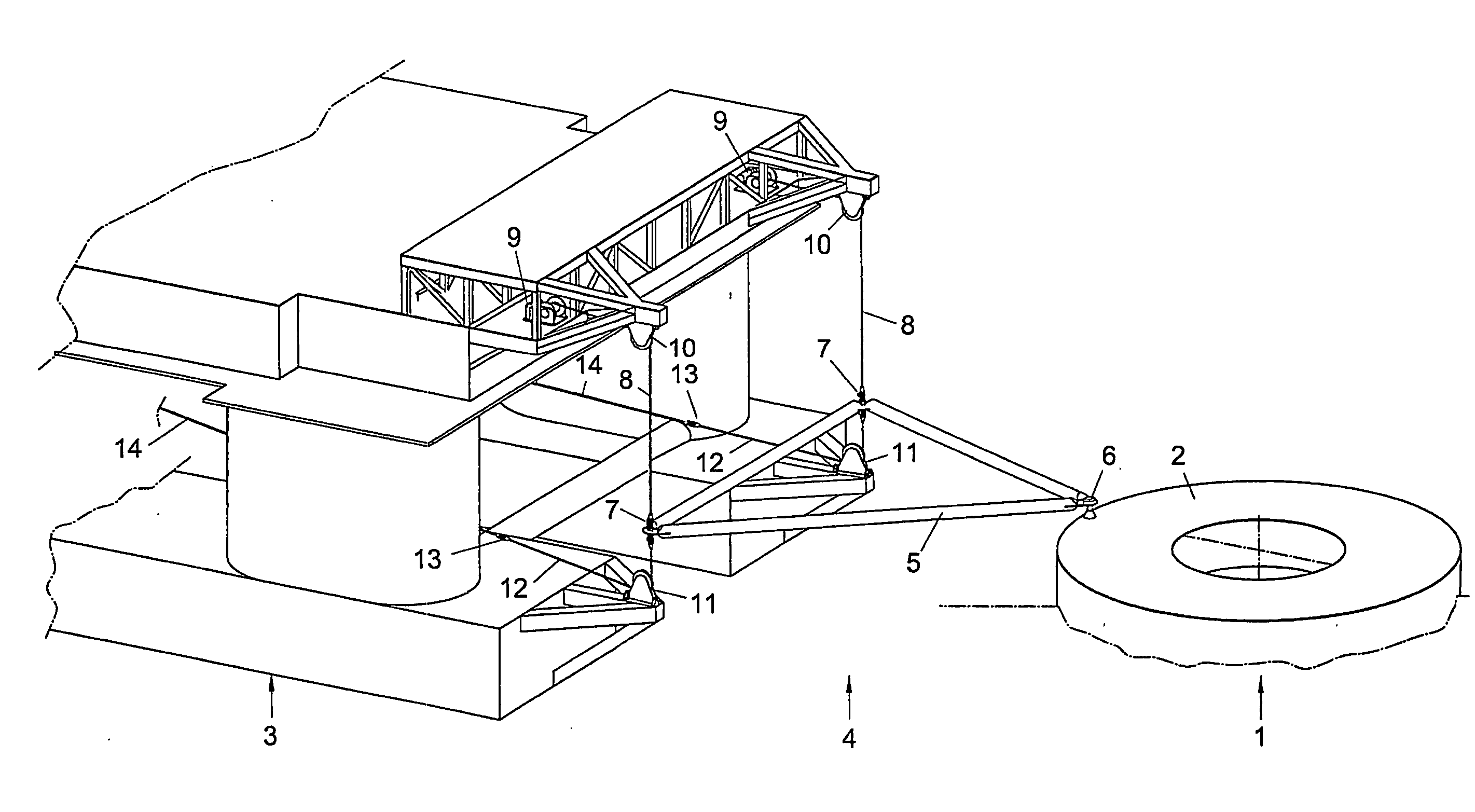
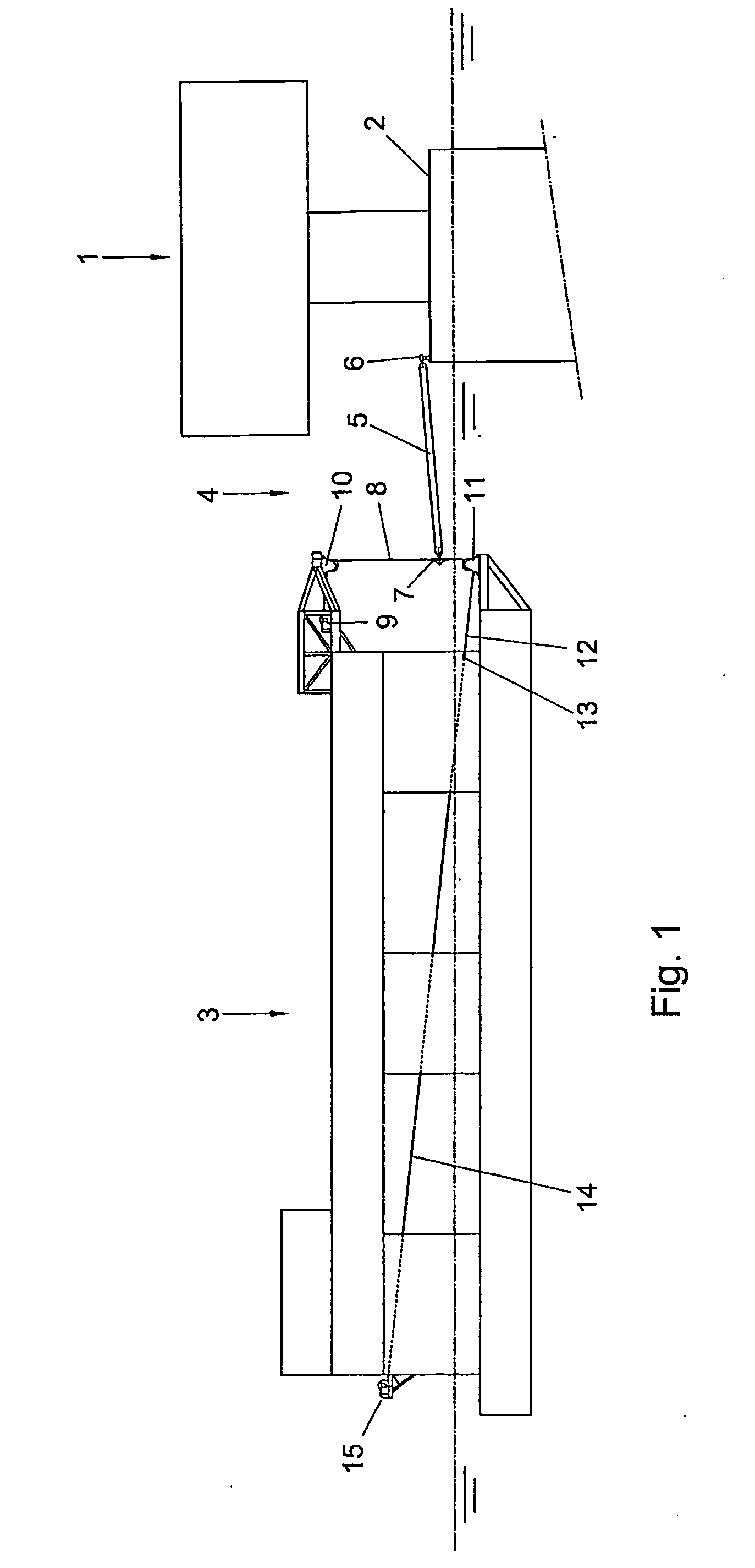
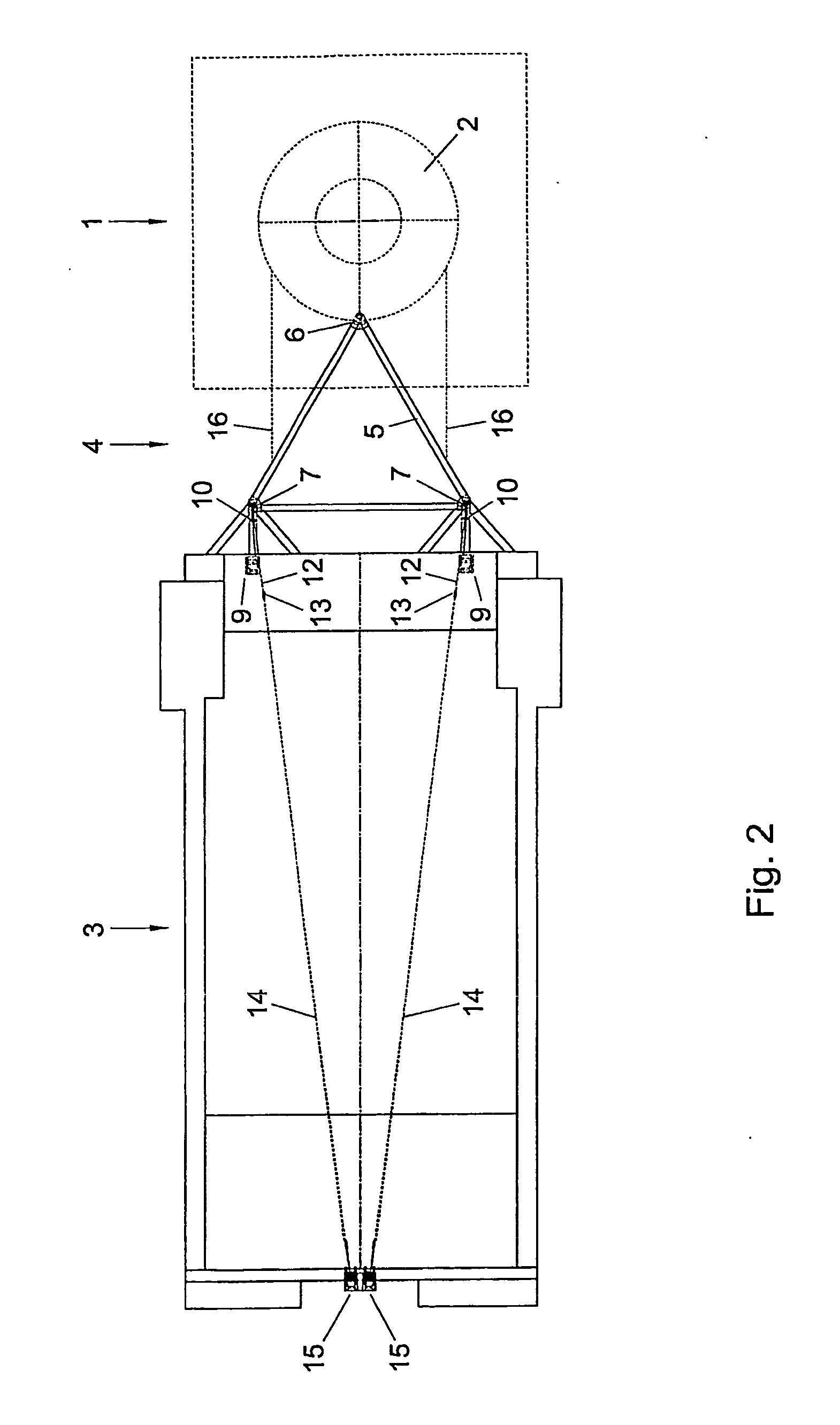
[0035] In FIGS. 1-3, a floating, anchored offshore unit in the form of a wellhead platform 1 is shown, which is provided with a deck 2 and is anchored to a bottom under water in a manner not shown. Further, FIGS. 1-3 show a floating offshore unit 1 in the form of a tender unit 3 moored in a manner not shown near the wellhead platform 1.

[0036] The wellhead platform 1 and the tender unit 3 are mutually coupled by a connecting apparatus 4, which is provided with a relatively rigid triangular frame 5, for instance formed by a rod construction, of which a first angular point bears a ball hinge 6, which is also fixed on the deck 2 of the wellhead platform 1, with which the coupling between the connecting apparatus 4 and the wellhead platform 1 has been brought about. The two other angular points of the triangular frame 5 are each connected, via connecting means 7 allowing pivotal movement and rotation, with a steel cable 8, which initially runs substantially horizontal from a winch 9 fix...


PUM


Abstract

A connecting apparatus for two offshore units includes a coupling element with two sets of couplings and resetting facilities that compensate movements between the two offshore units. The coupling element includes a frame connected with the offshore units by two sets of couplings in a manner allowing pivotal movement and rotation. At least one set of couplings includes a first and a second elongated element that are each connected with both the frame and an offshore unit via constructions allowing pivotal movement and rotation. The resetting facilities include a first and a second resilient element that are each stationary connected with the offshore unit and force either the first or the second elongated element to a position extending substantially vertically downwards.

Description

CROSS REFERENCE TO RELATED APPLICATIONS [0001] This application is the National Phase of International Application PCT / NL2005 / 000156, filed Mar. 3, 2005, which claimed priority to Netherlands Application 1025708, filed Mar. 12, 2004, the entire contents of both applications being incorporated herein by reference. BACKGROUND OF THE INVENTION [0002] 1. Field of the Invention [0003] The invention relates to an apparatus for connecting two offshore units and is provided with a coupling element which is, via a first set of coupling means, connectable with the one offshore unit and, via a second set of coupling means, with the other offshore unit, where, further, resetting facilities are present for compensating movements between the two offshore units. [0004] 2. Description of the Related Art [0005] Such a connecting apparatus is, for instance, used for connecting a tender drilling unit and a wellhead platform or a production platform. Such connecting apparatuses generally have a relativ...

Claims


Application Information

Patent Timeline
Patent Type & Authority Applications(United States)
IPC IPC(8): B63B21/00B63B22/02
CPCB63B22/025B63B21/00B63B22/02
Inventor KANT, ROBBERT
Owner MARINE STRUCTURE CONSULTANTS MSC
Learn More