Air bag inflator vibration damper

Active Publication Date: 2007-10-11
ARC AUTOMOTIVE
View PDF8 Cites 9 Cited by
  • Summary
  • Abstract
  • Description
  • Claims
  • Application Information

AI Technical Summary

Benefits of technology

[0015] This damper construction allows the inflator some freedom of movement so as to dampen vibration in the steering column and to eliminate the need for a separate damper system within the steering column. Also, the damper of the present invention can be mounted o

Problems solved by technology

They have been complicated in construction;
They have been difficult to install;
They have been difficult and/or expensiv

Method used


Image

  • Air bag inflator vibration damper
  • Air bag inflator vibration damper
  • Air bag inflator vibration damper

Examples


Example

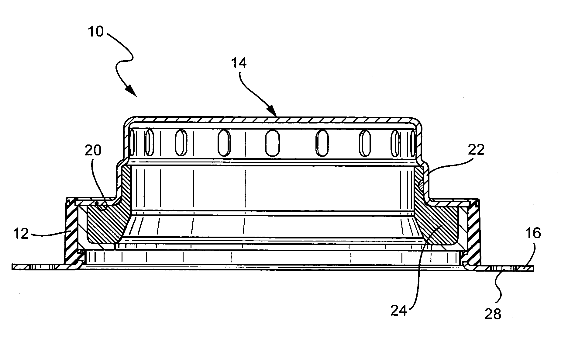
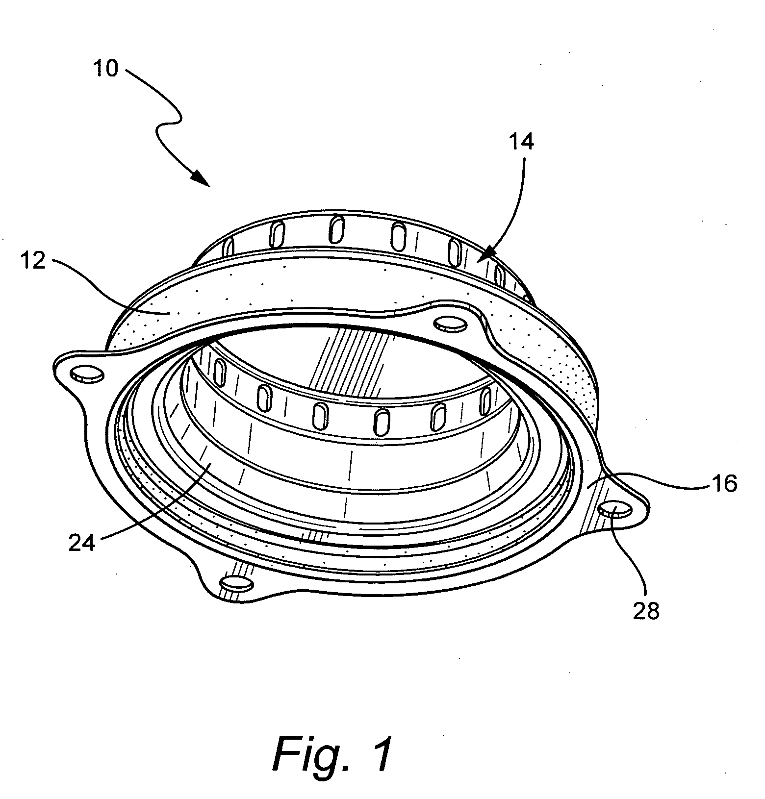
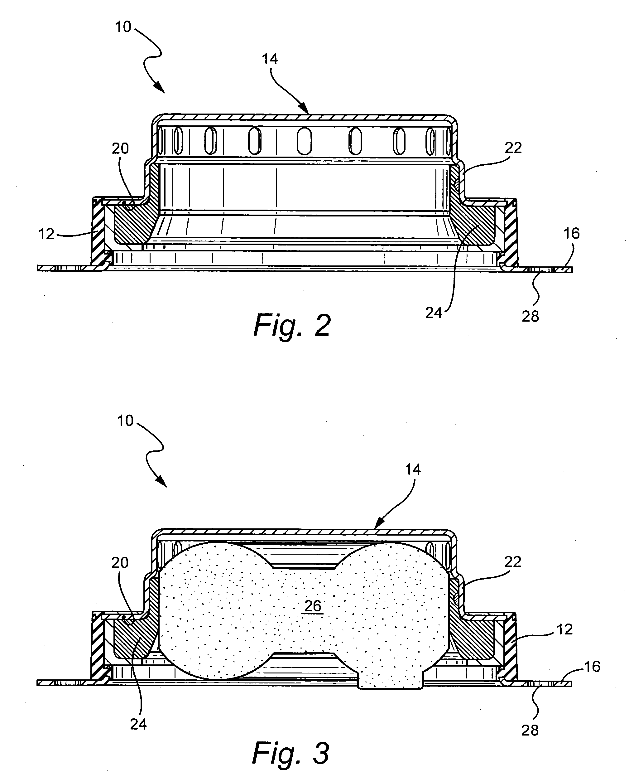
[0019] Referring to FIGS. 1-3, the vibration damper 10 of the present invention generally comprises an annular, flexible and resilient damper member 12 that is secured at its ends to first and second, substantially rigid interface members 14 and 16, respectively. The purpose of the vibration damper 10 is to connect an inflator to an air bag module in a motor vehicle steering column or the like for the purpose of allowing the inflator some freedom of movement so as to dampen vibration in the steering column.

[0020] As shown in FIGS. 2 and 3, the damper member 12 may be in the form of a truncated cone or may have any other suitable annular shape such as cylindrical. The damper member 12 may be formed of any suitable, flexible and resilient material such as rubber, thermoplastic elastomers, or thermoset elastomers.

[0021] At its upper or first end portion 18, the damper member 12 is secured in any suitable manner to the first interface member 14 which is the diffuser manifold for the i...


PUM


Abstract

A vibration damper for connecting an inflator to an air bag module in a vehicle steering column or the like. The vibration damper comprises a flexible and resilient, annular damper member having a first end portion connected to a diffuser for the inflator, and a second opposite end portion connected to an interface member. The diffuser is connected to an inflator ring that is constructed to be connected to the inflator. The interface member is constructed to be connected to the air bag module.

Description

BACKGROUND OF THE INVENTION [0001] 1. Field of the Invention [0002] The present invention relates to a vibration damper for an airbag inflator and, more particularly, to such a vibration damper which is positioned between an inflator and an airbag module in a steering column of a motor vehicle. [0003] 2. Description of Related Art [0004] The vibrations that arise in motor vehicles during movement or idling thereof with the motor running are, in many cases, transmitted to the steering column and then to the steering wheel. To dampen these vibrations at the steering wheel and to improve driving comfort, various types of vibration damper devices have been mounted within the steering column. In some cases, the vibration damper device has been integrated with the airbag inflator assembly mounted within the steering column and, in other cases, it has been separate therefrom. [0005] Such vibration damper devices have been subject to one or more of the following disadvantages: [0006] 1. The...

Claims


Application Information

Patent Timeline
IPC IPC(8): B60R21/217
CPCB60R21/2037B60R21/217B60R21/16B60R21/20
Inventor BOYD, TEDSTRONG, MIKE
Owner ARC AUTOMOTIVE
Why Eureka
Try Eureka