Projectile targeting analysis

Inactive Publication Date: 2007-10-11
GOVERMMENT OF THE UNITED STATES SEC OF THE NAVY
View PDF22 Cites 40 Cited by
  • Summary
  • Abstract
  • Description
  • Claims
  • Application Information

AI Technical Summary

Benefits of technology

[0016] It is further an additional object of the invention to predict the effects of the projectile in the impact zone.
[0017] It is a final object of the invention to collect digitized video of the projectile launcher's aimpoint during the aiming procedure to evaluate the shooter's aiming performance.
[0018] In order to accomplish the above objects, in accordance with a first aspect of the present invention there is provided an aimpoint tracking and data collection system for projectiles duri

Problems solved by technology

The aimpoint analysis of the 503′ patent is limited to a virtual environment with all targets displayed upon a video projection screen.
There are several disadvantages to live testing including technical obstacles to tracking the projectile.
For example, ballistic radar is the technology most commonly used to track the fall of shot, b

Method used


Image

  • Projectile targeting analysis
  • Projectile targeting analysis
  • Projectile targeting analysis

Examples


Example

[0036] In the following detailed description of the preferred embodiment, reference is made to the accompanying drawings in which is shown by way of illustration a specific embodiment whereby the invention may be practiced. It is to be understood that other embodiments may be utilized and changes may be made without departing from the scope of the present invention.

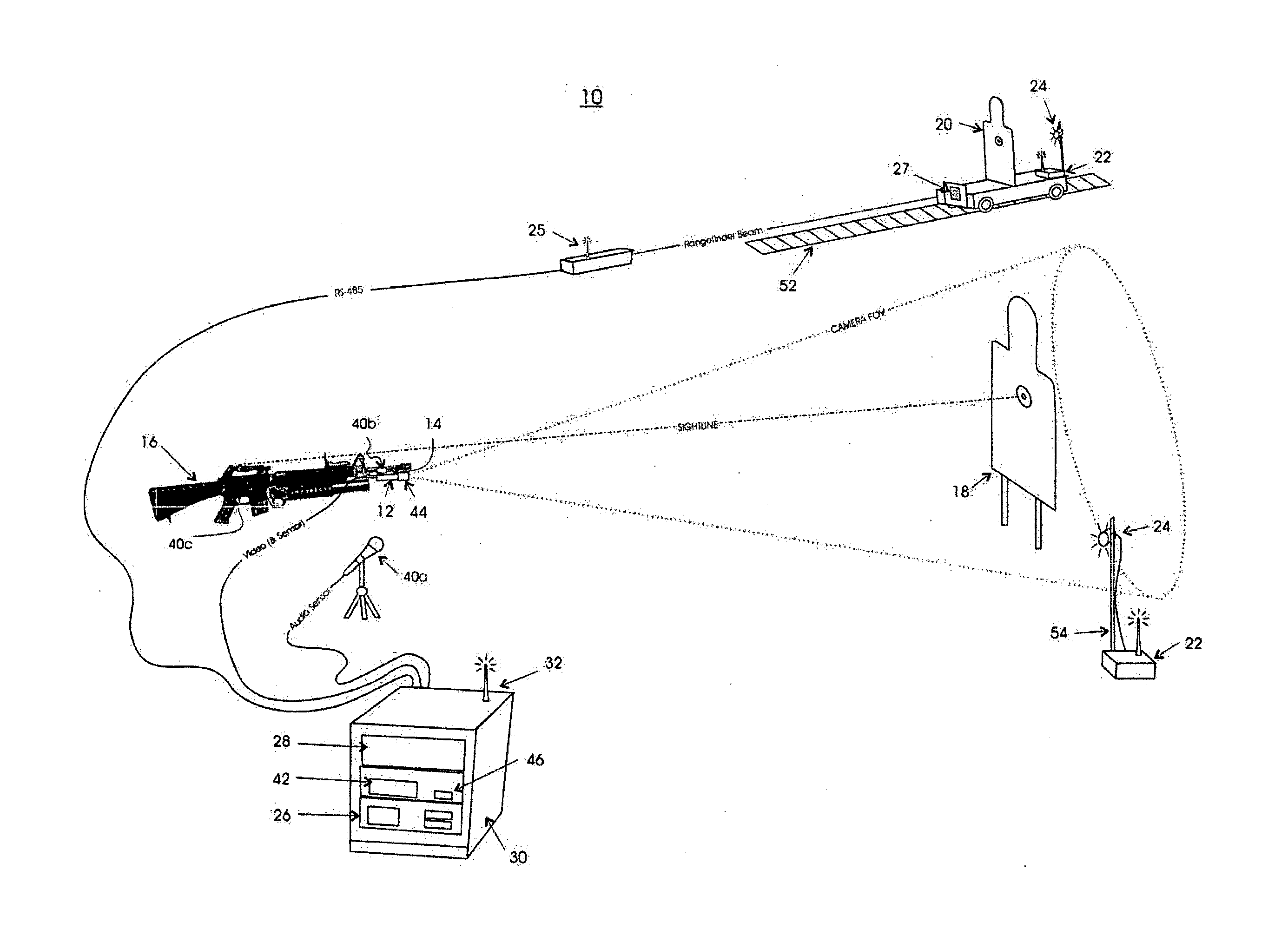
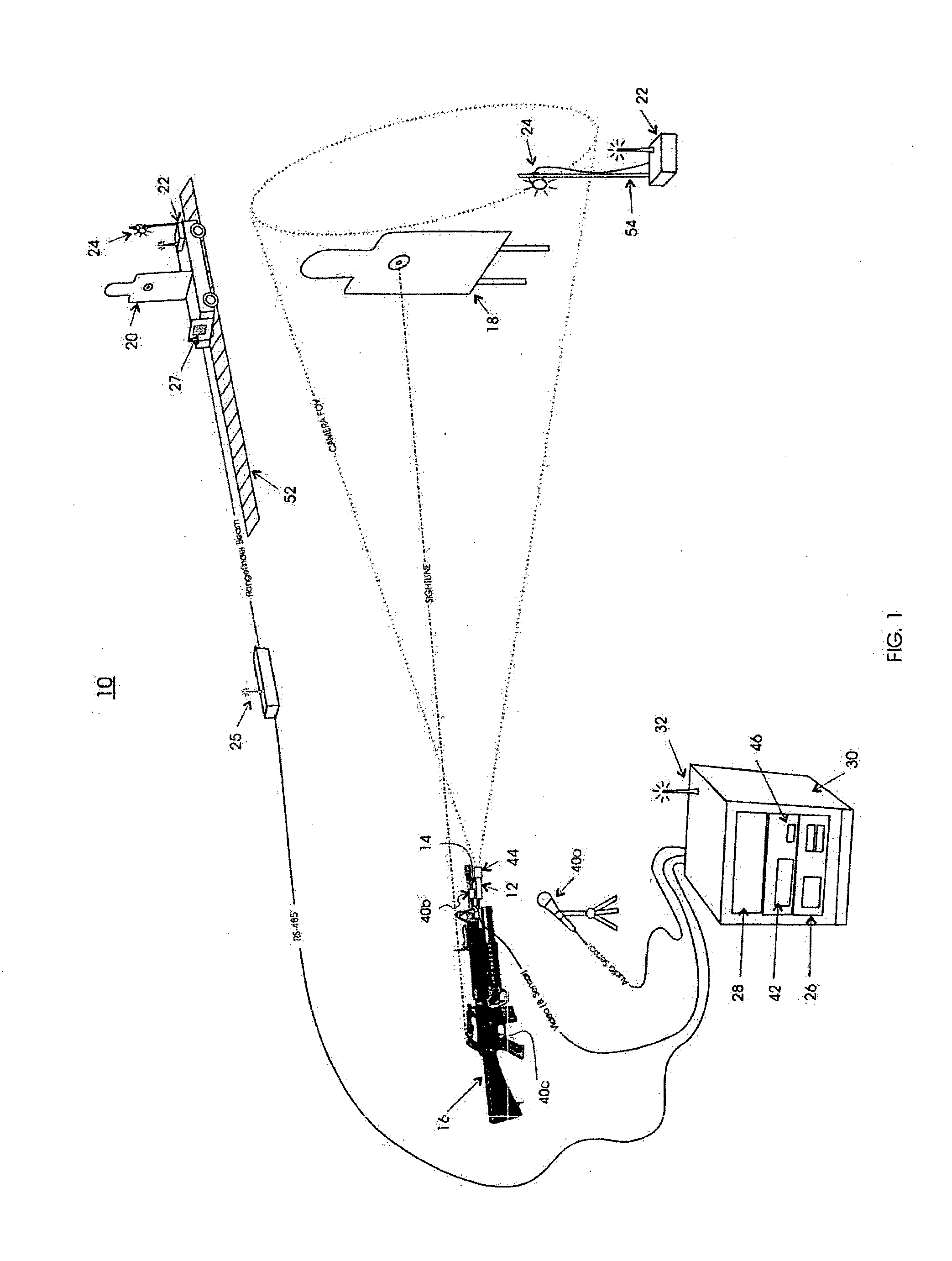
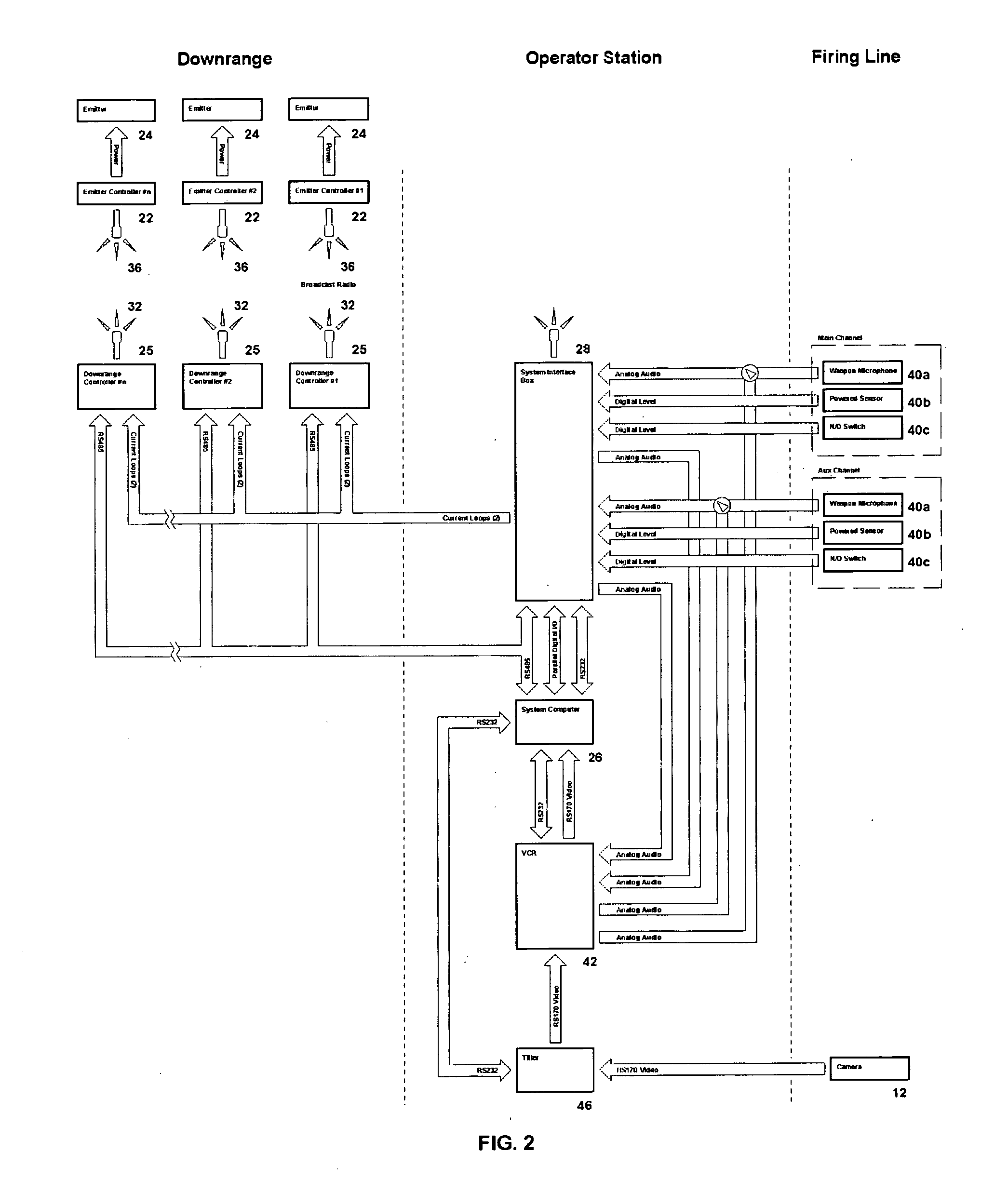
[0037] Referring to FIG. 1 and FIG. 2, an exemplary embodiment a projectile launcher aimpoint tracking system is shown generally at 10. A camera 12 is affixed to a mount 14, and the mount is affixed to a projectile launcher such as a rifle 16. Stationary targets 18 or moving targets 20 including both stationary and moving infrared emitters 24, respectively along with emitter controllers 22 are located in a firing range. A firing range is a volume where targets are located and can include an entire battle theatre. Infrared emitters 24, typically LED's or optically filtered halogen lamps, are located downrange as reference...


PUM


Abstract

An exemplary embodiment of the invention relates to determining aimpoint relative to a target located within a firing range. The target can be either fixed or moving, and if the target is moving then it can be mounted on tracks or controlled by servomechanisms. In addition to aimpoint, predicted projectile effects and personnel performance can be calculated for evaluation and for training. The firing range is mapped so that placement of infrared emitters is associated with specific targets. Placement of the emitter external to the target perimeter produces accurate results so long as the emitter is within the field of view of a camera mounted upon the projectile launcher. The invention results in large firing ranges with the ability to place targets wherever desired without decreasing aimpoint measurement accuracy.

Description

BACKGROUND OF THE INVENTION [0001] 1. Field of the Invention [0002] This invention relates generally to projectile targeting and more particularly to small projectile trajectory analysis. [0003] 2. Description of the Related Art [0004] Determination of aimpoint is well known. Aimpoint is used in actual field situations to determine a fire control solution. Aimpoint is also used in training weapons operators to sharpen their skills and to improve their performance. U.S. Pat. Nos. 4,804,325 and 5,213,503 each of which is incorporated herein by reference illustrate representative relevant techniques in the prior art. [0005] U.S. Pat. No. 4,804,325 discloses a weapons training simulator that predicts aimpoint and trajectory. The invention uses a sensor mounted on a weapon to generate a target position signal based on point sources located within the perimeter of simulated targets, thereby defining a diffusely illuminated target field. Set in a real-world environment the aimpoint is dete...

Claims


Application Information

Patent Timeline
IPC IPC(8): F41G3/26
CPCF41G3/2605G01S5/163F41G3/323F41G3/2661
Inventor PORTOGHESE, ROCCOHEBB, RICHARD CHRISTOPHERPURVIS, EDWARD JOHNPURVIS, JAMES EARL
Owner GOVERMMENT OF THE UNITED STATES SEC OF THE NAVY
Why Eureka
Try Eureka