Method And Apparatus For A Signal Selective RF Transceiver System

a transceiver and signal technology, applied in the field of wireless devices, can solve the problems of increasing the wireless network capacity, cross-talk and interference problems, and the problem is particularly serious, and achieve the effect of reducing the efficiency of the communication system, increasing cost and complexity

Active Publication Date: 2007-10-11
QUALCOMM INC
View PDF31 Cites 16 Cited by
  • Summary
  • Abstract
  • Description
  • Claims
  • Application Information

AI Technical Summary

Benefits of technology

[0010] The present inventors have realized the need to configure a plurality of adjacent wireless network circuits to operate simultaneously without reducing communication system efficiency and increasing cost and complexity. An aspect of the present invention is a radio frequency (RF) receiver including a RF filter circuit configured to dynamically select an available frequency range from a plurality of frequency ranges, and a RF processing circuit configured to signal process a RF signal passed through the RF filter circuit.

Problems solved by technology

One problematic issue relates to increasing wireless network capacity.
Unfortunately, transmitters and receivers of the wireless network cards placed in proximity to one another can cause cross talk and interference issues.
As just described, this problem is particularly serious when one wireless network card is transmitting while another is receiving.
Unfortunately, this methodology may require procuring and maintaining a stock of different wireless network cards for each narrow frequency sub-range.
All of the above solutions generally add complexity, reduce flexibility or performance, and increase the overall cost of the wireless network.

Method used


Image

  • Method And Apparatus For A Signal Selective RF Transceiver System
  • Method And Apparatus For A Signal Selective RF Transceiver System
  • Method And Apparatus For A Signal Selective RF Transceiver System

Examples


Embodiment Construction

[0021] In the following description, numerous specific details are set forth to provide a more thorough understanding of the present invention. However, upon review of the present disclosure, it will be apparent to one of ordinary skill in the art that the present invention may be practiced without one or more of these specific details. In other instances, well-known features have not been described in order to avoid obscuring the present invention. Aspects of the present invention are described in terms of wireless RF transmission and reception in an IEEE 802.11a and IEEE 802.11b regulated environment; however, other wireless transmission and reception environments are contemplated.

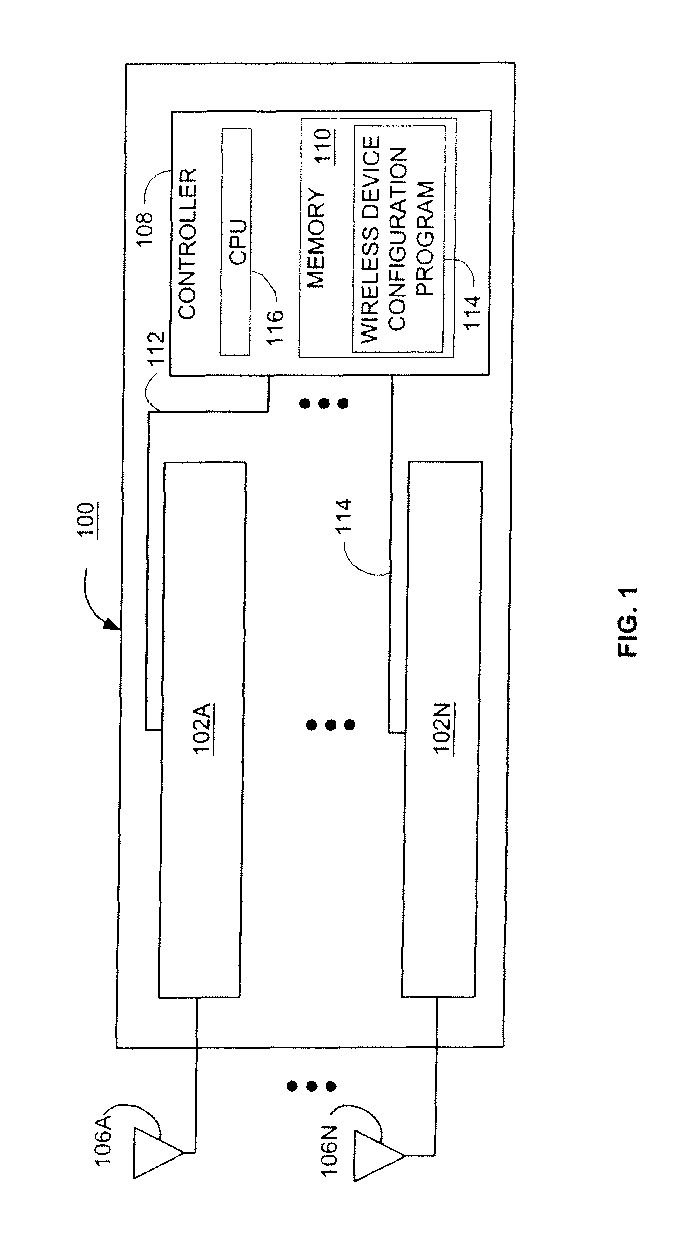
[0022]FIG. 1 is a high-level schematic diagram illustrating one embodiment of an exemplar wireless network system 100 in accordance with one or more aspects of the present invention. In general, wireless network system 100 may operate within a wireless local area network (LAN), a wireless wide area netw...


PUM


Abstract

Method and apparatus to dynamically configure the signal reception selectivity of a plurality of transceivers is described. In one embodiment, a transceiver includes a receiver circuit having two or more filter circuits. Each of the filter circuits is configured to pass RF signals from a different portion of an overall receiver bandwidth. When two or more receivers in proximity to one another are simultaneously operating, the filter circuits of the respective receiver are dynamically configured to different RF frequency passbands to minimize interference and cross talk between receivers and transmitters.

Description

COPYRIGHT NOTICE [0001] A portion of the disclosure of this patent document contains material which is subject to copyright protection. The copyright owner has no objection to the facsimile reproduction by anyone of the patent document or the patent disclosure, as it appears in the Patent and Trademark Office patent file or records, but otherwise reserves all copyright rights whatsoever. RELATED APPLICATIONS [0002] This application is a divisional of U.S. patent application Ser. No. 10 / 621,687, entitled “Method And Apparatus For A Signal Selective RF Transceiver System” filed Jul. 17, 2003. BACKGROUND OF THE INVENTION [0003] 1. Field of the Invention [0004] Embodiments of the present invention generally relate to wireless devices and more specifically to receiving and transmitting signals between transceivers. [0005] 2. Description of the Related Art [0006] Generally, a communication system includes a transmitter and receiver which transmit and receive information signals over a tra...

Claims


Application Information

Patent Timeline
Patent Type & Authority Applications(United States)
IPC IPC(8): H04B17/02H04B17/40
CPCH04B1/18H04W74/08H04W72/04
Inventor MCFARLAND, WILLIAM J.
Owner QUALCOMM INC
Why Eureka
Try Eureka