Supercharge Your Innovation With Domain-Expert AI Agents!

Navigation system

a technology of navigation system and wave based measurement system, applied in the field of navigation system, can solve the problems of increased error, increased error, increased error range, etc., and achieve the effect of reducing processing load

Active Publication Date: 2007-10-11
ALPINE ELECTRONICS INC
View PDF6 Cites 17 Cited by
  • Summary
  • Abstract
  • Description
  • Claims
  • Application Information

AI Technical Summary

Benefits of technology

"The present invention provides a navigation system that improves the correction accuracy of positioning error by using an estimated error range that takes into account the position of the GPS receiver, the velocity and travel angle of the vehicle, and the accuracy of the measured position. The navigation system includes a GPS receiver, an error-range-setting section, and a position correction section. The estimated error range is set based on the velocity and travel angle of the vehicle, and the position correction section corrects the measured position based on the estimated error range. The navigation system can improve the correction accuracy of positioning error even when the actual measured position is out of the estimated error range."

Problems solved by technology

Thus, there is a problem in that error is increased.
In this method, even when the measured position is expected to be in the estimated error range, the corrected measured position may be out of the estimated error range (in particular, when the actual measured position is greatly out of the estimated error range).
Thus, there is a problem in that error can be increased.
For example, since it is considered that the accuracies of a velocity and a travel direction detected with a GPS receiver are high, the possibility that an error-free measured position is in the estimated error range is considerably increased when the current measured position is assumed to be correct.

Method used


Image

  • Navigation system
  • Navigation system
  • Navigation system

Examples


first embodiment

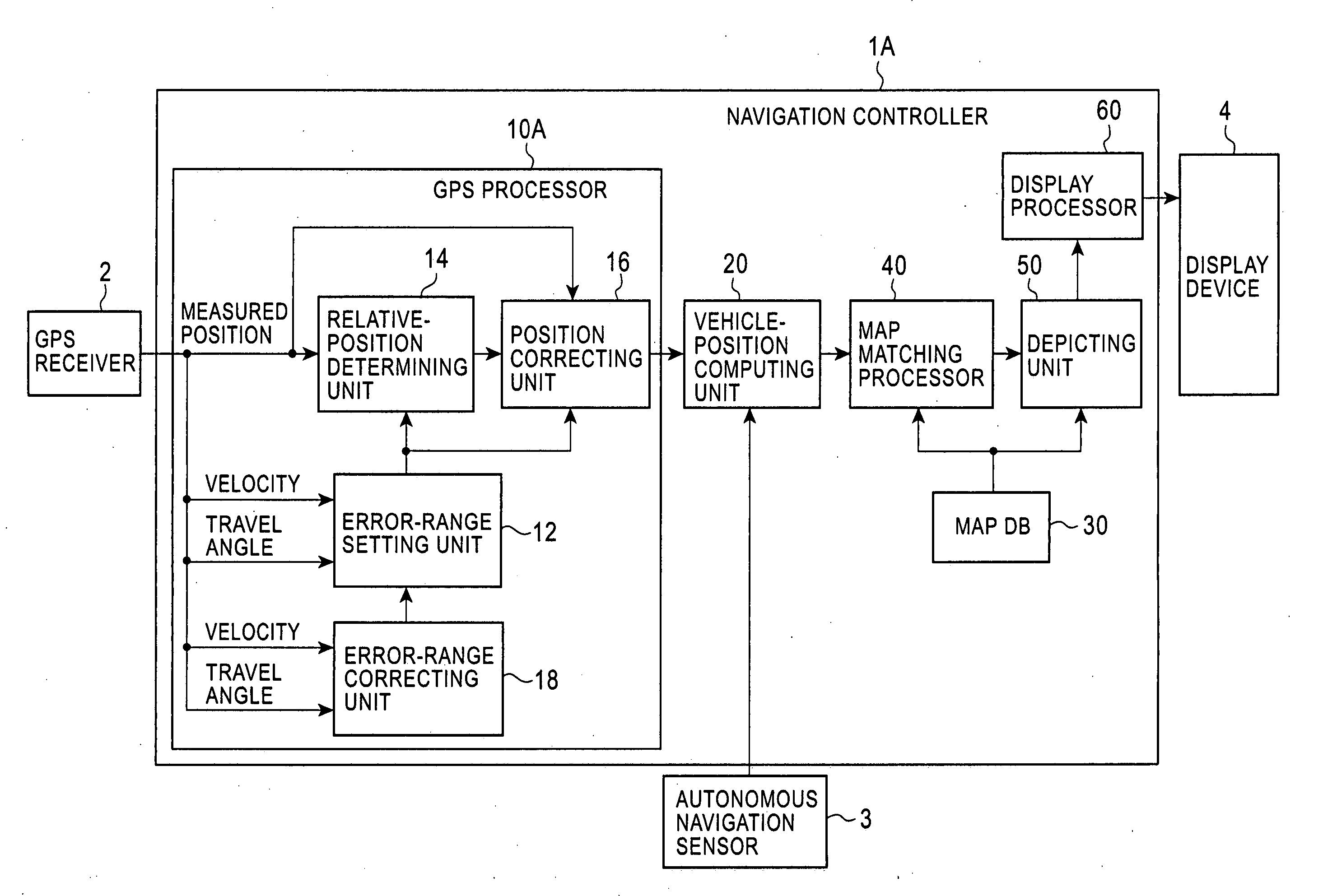
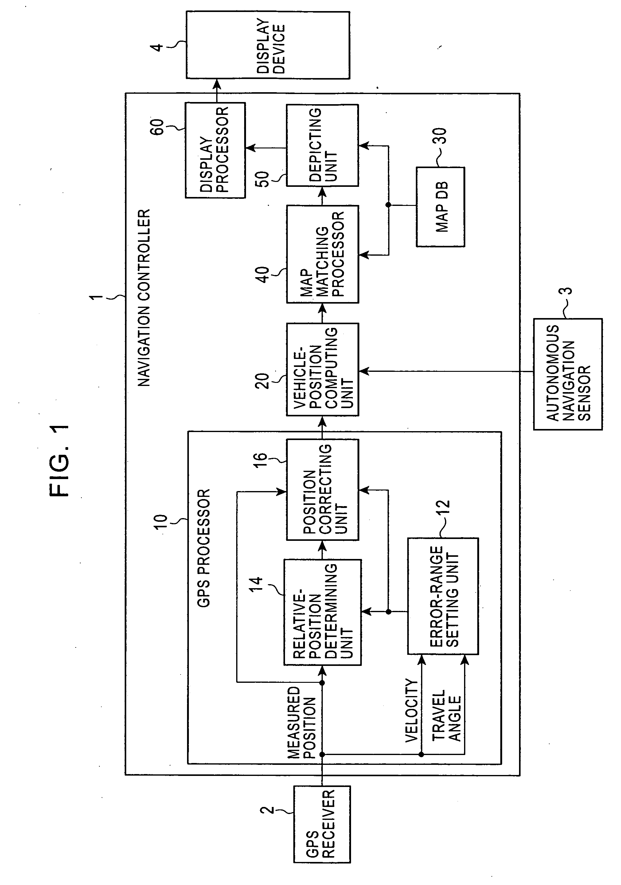
[0032]FIG. 1 is a diagram showing the configuration of a navigation system according to a first embodiment. The navigation system shown in FIG. 1 includes a navigation controller 1, a GPS receiver 2, an autonomous navigation sensor 3, and a display device 4.

[0033] The navigation controller 1 controls the entire navigation system. By using, for example, a CPU, ROM, and RAM, the navigation controller 1 executes a predetermined operation program to achieve its function.

[0034] The GPS receiver 2 receives radio waves transmitted from multiple GPS satellites, performs two-dimensional or three-dimensional positioning, and produces the absolute position (the measured position), the velocity, and the direction (the travel angle) of a vehicle. The autonomous navigation sensor 3 includes an angle sensor, such as a gyroscope, for detecting a vehicle rotation angle as a relative angle and a distance sensor for generating a pulse at each predetermined distance, and produces the relative positio...

second embodiment

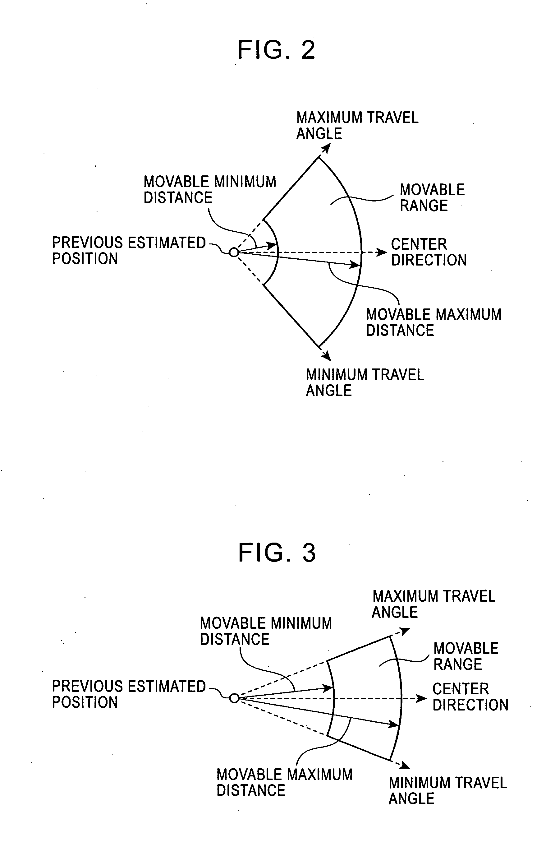
[0066] The navigation system of the first embodiment described above sets the orientation (i.e., the center directions shown in FIGS. 2 and 3) of the estimated error-range corresponding to the current positioning time, in accordance with the vehicle travel direction at the previous positioning time. However, when the vehicle travel direction changes greatly as in the case of a winding road and the vehicle exhibits circular motion, the vehicle travel angle at the previous positioning time and the vehicle travel angle at the current positioning time differ from each other. In such a case, therefore, it is desirable to correct the orientation of the estimated error range by considering the amount of change in the travel angle.

[0067]FIG. 7 is a diagram showing the configuration of a navigation system according to a second embodiment. The navigation system of the second embodiment shown in FIG. 7 is different from the navigation system of the first embodiment shown in FIG. 1 in that an ...


PUM


Abstract

A navigation system includes a GPS receiver for receiving radio waves transmitted from multiple GPS satellites and producing a measured position, an error-range setting unit for setting an estimated error range in which a measured position at the time of current positioning by the GPS receiver is included, a relative-position determining unit, and a position correcting unit. The relative-position determining unit and the position correcting unit correct the measured position by using an actual measured position, when the actual measured position produced by the GPS receiver at the current positioning time is in the estimated error range. The relative-position determining unit and the position correcting unit correct the measured position in accordance with a relative positional relationship between the actual measured position and the estimated error range, when the actual measured position is out of the estimated error range.

Description

BACKGROUND OF THE INVENTION [0001] 1. Field of the Invention [0002] The present invention relates to a navigation system that corrects a measured position obtained by using a GPS receiver, and that uses the corrected measured position. [0003] 2. Description of the Related Art [0004] It has been conventionally known that a measured position obtained by using a GPS receiver varies due to error factors, such as multipaths, and a navigation system that corrects the measured position so as to reduce an influence caused by the error is known (refer to, e.g., Japanese Unexamined Patent Application Publication No. 8-313278, pages 5 to 8 and FIGS. 1 to 3). The navigation system estimates the current measured position based on the previous measured position to set an estimated error range. When the current measured position is in the estimated error range, the navigation system uses the actual measured position, and when the current measured position is out of the estimated error range, the n...

Claims


Application Information

Patent Timeline
Patent Type & Authority Applications(United States)
IPC IPC(8): G01C21/00G01S19/40G01S19/49G01S19/50G01S19/52
CPCG01C21/28
Inventor WATANABE, TAKAYUKIWAKAMATSU, KOUTAROMORI, DAISHIMINAMI, MASANA
Owner ALPINE ELECTRONICS INC
Features
  • R&D
  • Intellectual Property
  • Life Sciences
  • Materials
  • Tech Scout
  • Unparalleled Data Quality
  • Higher Quality Content
  • 60% Fewer Hallucinations
Learn More