
Authentication network system

a network system and authentication network technology, applied in the field of authentication network system, can solve the problems of difficult management, inability to take the configuration of managing biometric information in the server on the network, inability to communicate biometric information etc., and achieve the effect of ensuring the high security of the network

Inactive Publication Date: 2007-10-11
FUJITSU LTD
View PDF14 Cites 23 Cited by
  • Summary
  • Abstract
  • Description
  • Claims
  • Application Information

AI Technical Summary

Benefits of technology

[0076]According to the present invention, it is possible to provide the technology enabling the establishment of the compatibility between providing the convenience for the user who inputs the authentication information and ensuring the high security of the network.

Problems solved by technology

Thus, if configured to register the information in each of the PCs, for example, on the occasion of registering and updating the information, it follows that the registering and updating operations are executed for each PC, and hence, if scaled up to a certain or greater degree, the management gets hard to do.
Therefore, a desired configuration is a configuration for managing in a centralized way the information of the IC card and the biometric information of the user by registering these items of information in a server on the network, however, if in the case of the network's being unconnectable till the authentication is completed as described above, the network is still unutilizable when conducting the authentication, so that it is impossible to take the configuration for managing the biometric information in the server on the network.
Namely, when conducting this authentication, it was unfeasible to communicate the biometric information etc without any restriction, though capable of communicating the information such as the ID and the password that are defined by an authentication protocol.

Method used


Image

  • Authentication network system
  • Authentication network system
  • Authentication network system

Examples


first embodiment

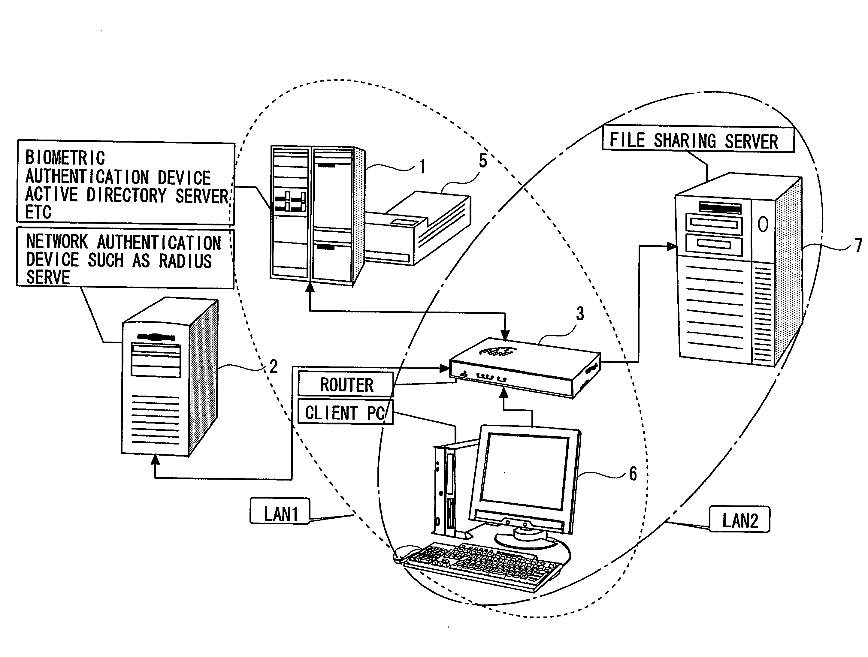
[0085]FIG. 1 is a schematic view of an authentication network system according to the present invention. An authentication network system 10 in the first embodiment is configured by a fingerprint authentication device (a first authentication device) 1, a RADIUS server (Remote Authentication Dial In User Service server: a second authentication device) 2, a router (a connection control device) 3, etc.

[0086]The authentication network system 10 in the first embodiment has a LAN 1 and a LAN 2, which are logically different from each other, owing to a function of VLAN (Virtual Local Area Network).

[0087]The LAN 1, to which the fingerprint authentication device 1, a network printer 5, etc belong, is an open network to which a terminal (a communication device) 6 before being authenticated is connected.

[0088]The LAN 2 is a network, to which an in-office file server 7 etc belongs, is a network to which the terminal 6 after being authenticated can be connected.

[0089]In the authentication networ...

second embodiment

[0139]FIG. 7 is a schematic view of the authentication network system in a second embodiment according to the present invention. The second embodiment is different from the first embodiment described above in terms of a point of using a plurality of LAN switches as the connection control devices. Other configurations are substantially the same, and therefore the repetitive explanations are omitted by marking the same components with the same numerals and symbols.

[0140]Each of the LAN switches 3A, 3B includes the port 32, the connecting unit 33 and the receiving unit 34 and the connection switchover unit 35 described above.

[0141]With this configuration, as in the first embodiment discussed above, when the terminal 6 connected to the ports 32 of the respective LAN switches 3A, 3B logs on, the user authentication 1 and the user authentication 2 are carried out. Then, when receiving from the RADIUS server 2 the information showing the purport that terminal 6 is authenticated, the connec...


PUM


Abstract

To provide a technology enabling establishment of compatibility between providing convenience for a user inputting authentication information and ensuring high security of a network. An authentication network system of the present invention is comprised so that: a first authentication device receives first authentication information via a first network from a communication device, judges whether the first authentication information is authenticated or non-authenticated and, if the first authentication information is authenticated, notifies of the second authentication information; a second authentication device receives the second authentication information, judges whether the second authentication information is authenticated or non-authenticated by comparing the second authentication information with information registered beforehand and, if the second authentication information is authenticated, notifies a connection control device; and the connection control device switches over the connection of the authenticated communication device to a second network from the first network.

Description

BACKGROUND OF THE INVENTION[0001]The present invention relates to a technology of authenticating a terminal connected to a network.[0002]Over the recent years, it has increasingly been important to ensure the security in a network such as a LAN (Local Area Network). Hence, for instance, such a technology was proposed that a computer (PC: Personal Computer) connected to the LAN is authenticated but can not be connected to the LAN unless it is the permitted PC. The IEEE802.1x standards give a definition of a technology of conducting the authentication when connected to the network.[0003]In the case of carrying out this authentication, as a general rule, a user inputs necessary items of information for the authentication (authentication information) such as an ID and a password to the PC, and the PC transmits these items of information to an authentication server.[0004]It is to be noted that operations (schemes) such as periodically changing the password, making the password difficult ...

Claims


Application Information

Patent Timeline
Patent Type & Authority Applications(United States)
IPC IPC(8): H04L9/32G06F21/31G06F21/32
CPCH04L63/08H04L63/083H04L63/0861H04L63/0892H04L63/10H04L9/32H04L12/28
Inventor SOMEKAWA, JUNTAKABA, KOICHI
Owner FUJITSU LTD
Learn More