Eureka AIR delivers breakthrough ideas for toughest innovation challenges, trusted by R&D personnel around the world.

Lay out line

a chalk and line string technology, applied in the field of chalk depositing devices, can solve the problems of increasing the already slow and cumbersome nature of chalk depositing, affecting the quality of chalk depositing, and unable to provide reliably-spaced indicia of chalk depositing strings

Inactive Publication Date: 2007-10-18
STUDLINE TOOL
View PDF8 Cites 13 Cited by
  • Summary
  • Abstract
  • Description
  • Claims
  • Application Information

AI Technical Summary

Benefits of technology

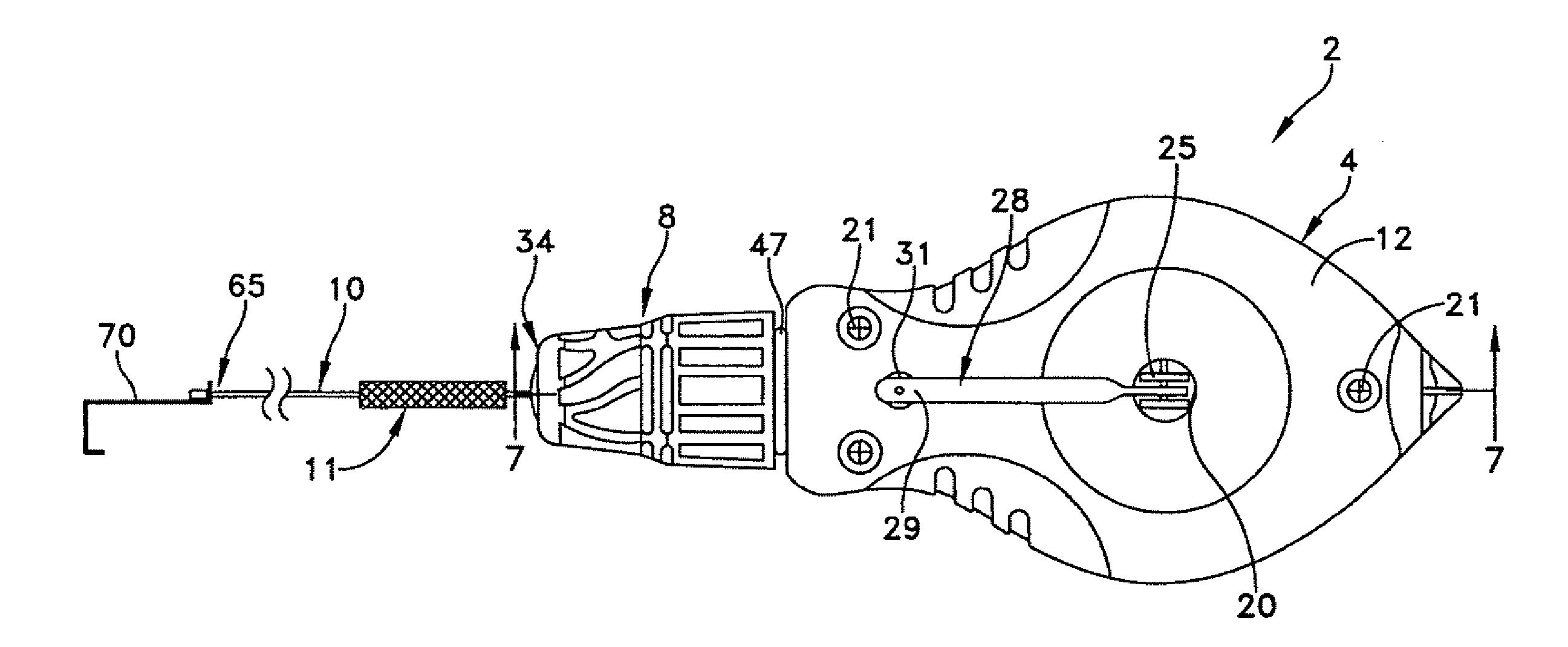
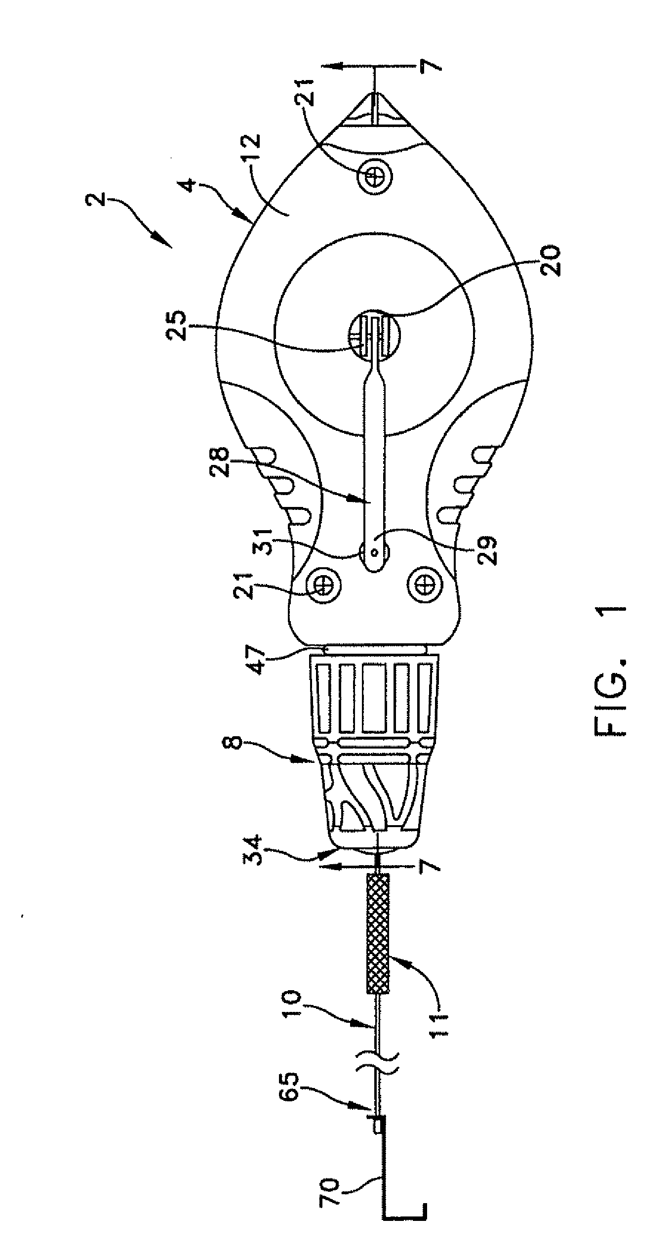
[0010] A tensioned chalk line apparatus is further disclosed, comprising: a chalk line comprising a multi-strand line, said chalk line having a relaxed configuration in which substantially no tensile force is applied to said chalk line and a tensed configuration in which a predetermined tensile force is applied to an end of said chalk line, said chalk line further having a length that is shorter in said relaxed configuration than in said tensed configuration. The chalk line may further have a plurality of surface discon...

Problems solved by technology

The workman is usually on his or her knees or on a ladder during this process, which adds to its already slow and cumbersome nature.
The disadvantages of such chalk-line strings are manifold.
Firstly, such prior art chalk-line strings do not provide reliably-spaced indicia because the length of a string will vary (i.e., stretch or shrink) to some extent with changes in temperature and humidity; strings increase in length or stretch when under tension, e.g., during snapping, and strings increase in length and become weak after prolonged use.
Secondly, such chalk-line strings provide narrowly spaced voids or chalk-free areas which are difficult to locate along the chalk line marking unless they are spaced fairly wide apart, in which case they do not provide an accurate measurement guide.
Also, if the chalk line marking is weak in intensity and / or is inadvertently contacted or smeared, voids may appear in unintended areas which can mislead the workman.
Furthermore, paint or other materials applied to the string surface can wear off, particularly under the effects of repeated transport of the string through the narrow eyelet provided on most prior art devices.

Method used


Image

  • Lay out line
  • Lay out line
  • Lay out line

Examples


Embodiment Construction

[0026] This description of preferred embodiments is intended to be read in connection with the accompanying drawings, which are to be considered part of the entire written description of this invention. The drawing figures are not necessarily to scale and certain features of the invention may be shown exaggerated in scale or in somewhat schematic form in the interest of clarity and conciseness. In the description, relative terms such as “horizontal,”“vertical,”“up,”“down,”“top” and “bottom” as well as derivatives thereof (e.g., “horizontally,”“downwardly,”“upwardly,” etc.) should be construed to refer to the orientation as then described or as shown in the drawing figure under discussion. These relative terms are for convenience of description and normally are not intended to require a particular orientation. Terms including “inwardly” versus “outwardly,”“longitudinal” versus “lateral” and the like are to be interpreted relative to one another or relative to an axis of elongation, o...


PUM


Abstract

A chalk line apparatus for marking regularly spaced locations. The apparatus comprises a casing for powdered chalk containing a rotatable reel, line wound on said reel, and an exit opening for the line at one end of the holder. The line has evenly spaced short segments disposed thereon so that when the line is tensioned to a predetermined level of about 10-15 lbs, the segments reside at precisely placed predetermined intervals. When the line is snapped, chalk marks are placed on the wall surface in a pattern that identifies the appropriate locations of underlying wall studs.

Description

CROSS REFERENCE TO RELATED APPLICATIONS [0001] This is a continuation-in-part application of pending non-provisional patent application Ser. No. 11 / 265,643, filed Nov. 2, 2005, by Hickey et al., titled “Lay Out Line,” which is a non-provisional patent application of U.S. provisional patent applications 60 / 669,284, filed Apr. 7, 2005, by Hickey et al., titled “Lay Out Line,” and 60 / 625,462, filed Nov. 5, 2004, by Hickey et al., titled “Layout Line,” the entirety of which applications are expressly incorporated herein.FIELD OF THE INVENTION [0002] The present invention generally relates to devices for depositing calibrated chalk markings on construction surfaces, and more particularly for depositing a line of chalk with visibly distinct markings at even intervals along its length for indicating the location of underlying wall studs. BACKGROUND OF THE INVENTION [0003] In the construction trades and in related fields, it is a constant requirement to position studs, posts, walls, partiti...

Claims


Application Information

Patent Timeline
IPC IPC(8): B44D3/38
CPCB44D3/38
Inventor HICKEY, JAMES KARLCRANSTON, MICHAEL THOMAS
Owner STUDLINE TOOL
Why Eureka
Eureka Blog
Learn More