Energization control apparatus and method for glow plug during the period from preglow to afterglow steps

Inactive Publication Date: 2007-10-18
DENSO CORP
View PDF5 Cites 25 Cited by
  • Summary
  • Abstract
  • Description
  • Claims
  • Application Information

AI Technical Summary

Benefits of technology

[0026]The present invention has been made in view of the above mentioned circumstances, and has an object to provide a glow plug control apparatus for controlling supply of electric power to both a glow plug and a starter from a power source, the starter assisting start of the engine by using the glow plug. The control apparatus comprises a starter switch allowing the electric power to be supplied to both the glow plug and the starter from the power source when the engine is cranked, a detecting device detecting a state of the engine, a calculating circuit calculating a pre-glow time, an after-glow time, a delay time. The delay time depends on both the detected state of the engine detected by the detecting device and a timing when the starter switch is turned on thereof, the delay time being defined as a time interval between a first time moment when the starter switch is turned to the power-on position and a second time moment when the electric power is started to be supplied to the glow plug. The pre-glow time is defined as a time interval during which the electric power is supplied to the glow plug so that temperature of the glow plug is raised. The after-glow time is defined as a time interval during which the electric power is supplied to the glow plug after the engine is started, and a control circuit controlling the supply of the electric power to both the glow plug and the starter based on the delay time, the pre-glow time, and the after-glow time which are calculated by the calculating device.
[0027

Problems solved by technology

That is, ignition of the fuel-air mixture may not be successful in an earlier stage of the diesel engine starting in which the diesel engine is as cold as the fuel-air mixture, since compression heat is not sufficient.
However, the very large inrush current is unavoidably applied to the low-rated-voltage type glow plugs because of the low initial resistance thereof.
This phenomena leads to the reduction of an output voltage of the battery, and to the failure of starting up the diesel engine since the glow plugs and the starter can not be supplied enough electric power from the battery to work efficiently.
Even when the output voltage of the battery is kept at a normal level, coinciding the starting timing of both preheating of the glow plug and starter ignition may result in expediting the consumption of the battery because of the large scale of the inrush current flowing through both the glow plug and starter.
However in this case, the diesel engine may sometimes fail to start since sufficient electric power for heating the glow plug and for driving the starter is not obtained.
It is difficult to use this method because there is no room for the bigger battery to be located in the engine room for the modern complicated engine system.
Thus,

Method used


Image

  • Energization control apparatus and method for glow plug during the period from preglow to afterglow steps
  • Energization control apparatus and method for glow plug during the period from preglow to afterglow steps
  • Energization control apparatus and method for glow plug during the period from preglow to afterglow steps

Examples


first embodiment

[0051]Referring to FIGS. 1 to 9, 16 to 17, a first embodiment of a glow plug energization apparatus will now be described.

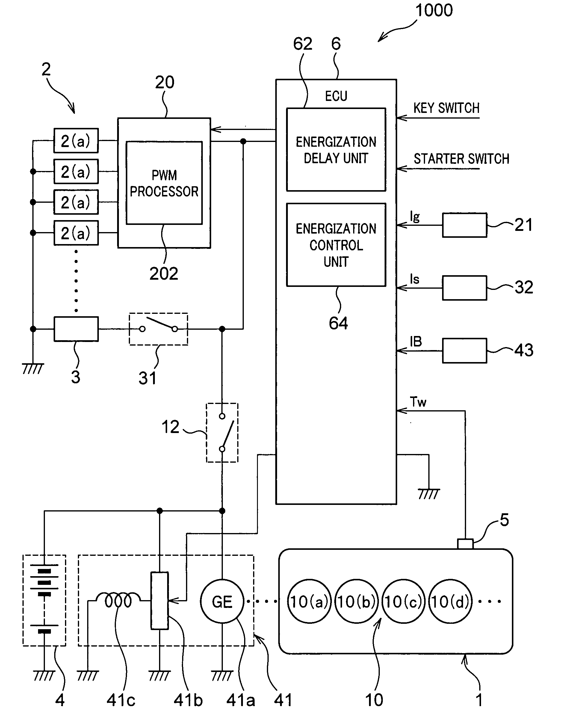
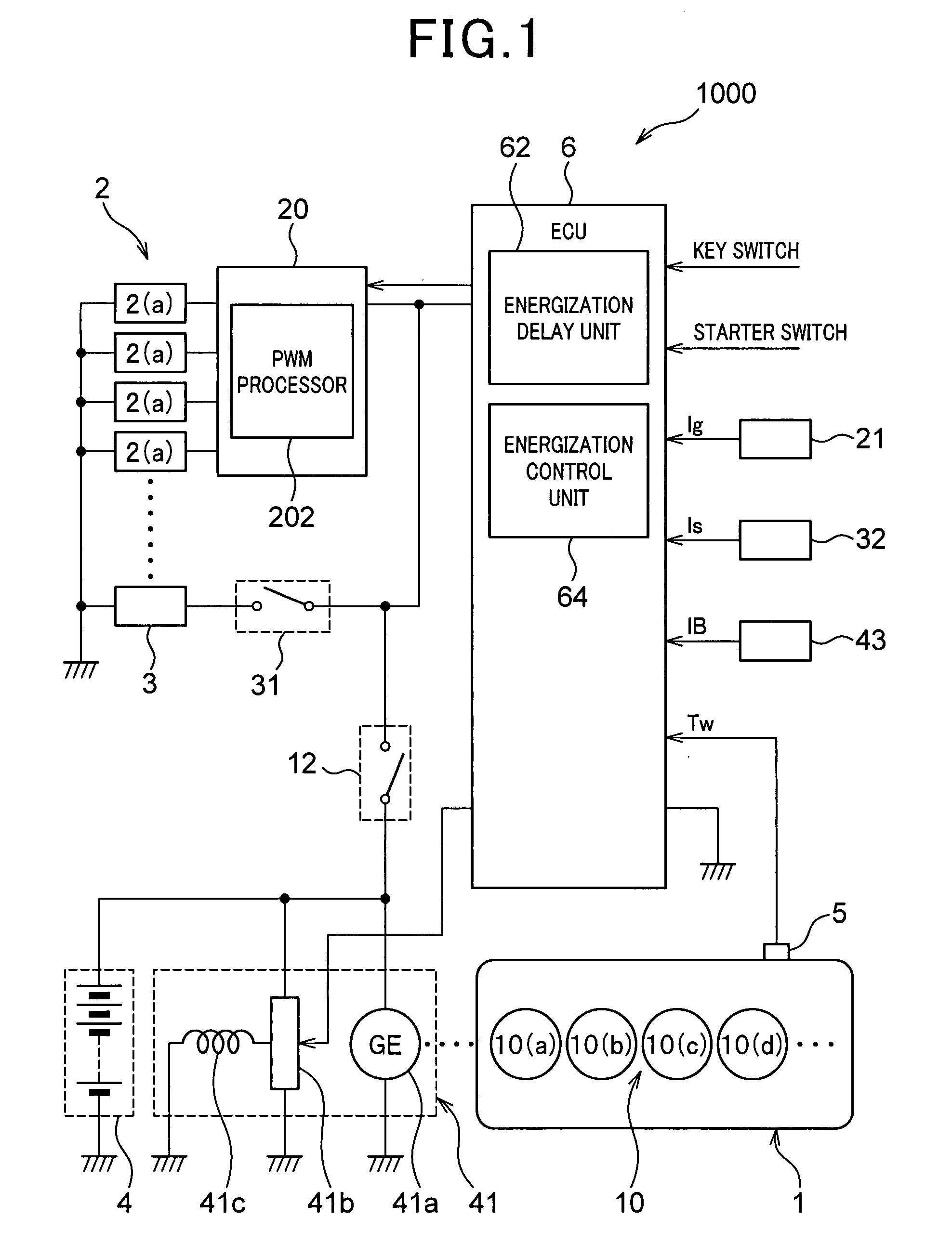
[0052]FIGS. 1 and 16 show a glow plug energization control apparatus 1000 according to the present invention and a diesel engine 1 (hereinafter, is abbreviated as “engine” for simplicity). The glow plug energization control apparatus is connected to the engine 1. The glow plug energization control apparatus 1000 according to the present invention includes, a glow plug controller 20 for controlling a voltage applied to glow plug using pulse width modulation (PWM) method, an electronic control unit (ECU) 6, an alternator 41, a battery 4, a power-source voltage detecting apparatus 43 for detecting a voltage outputted from the power source, a glow current detecting apparatus 21 for detecting current injected to the glow plug, a starter current detecting apparatus 32 for discriminating current injected to the starter, an engine water temperature detecting apparatus 5 ...

second embodiment

[0164]Referring to FIGS. 1, 10 to 13, 16, and 18 a second embodiment of a glow plug energization apparatus will be now described. In the second embodiment, the same reference numerals will be given to the identical and similar components in structures and / or functions to those in the first embodiment for the simplicity.

[0165]In the case where a timing when the starter switch 31 is not turned on is delayed for some time since the key switch 12 has been turned on, it may be happened that the temperature of the glow plug 2 has been sufficiently raised and the glow plug current flowing through the glow plug 2 has been decreased.

[0166]In this situation, it is not necessary to forbid the electric power supply to the glow plug 2 before the starter 3 is actuated.

[0167]The glow plug energization control apparatus according to the second embodiment of the present invention is connected to the diesel engine (hereafter is abbreviated as “engine” for simplicity).

[0168]As shown in FIGS. 1 and 16,...


PUM


Abstract

A control apparatus for controlling to supply of electric power to both a glow plug and a starter from a power source, the starter assisting start of the engine by using the glow plug, is provided. The control apparatus comprises a starter switch, starter, a detecting device detecting a state of the engine, a calculating circuit calculating a pre-glow time, an after-glow time, and a delay time. These times depend on both the detected state of the engine detected by the detecting device and a timing when the starter switch is turned on to a power-on position thereof. The control circuit controls the supply of the electric power to both the glow plug and the starter based on the delay time, the pre-glow time, and the after-glow time.

Description

CROSS REFERENCE TO RELATED APPLICATION[0001]The present application relates to and incorporates by reference Japanese Patent Application No. 2006-110813 filed on Apr. 13, 2006.BACKGROUND OF THE INVENTION[0002]1. The Field of the Invention[0003]The present invention relates to an apparatus and a method for controlling a glow plug, and more particularly to an apparatus and a method for controlling electronic power supplied to the glow plug so as to assure activation and running in a steady state of a diesel engine of an automotive vehicle whenever an operator of the automotive vehicle turns key switch on.[0004]2. Description of the Prior Art[0005]A Diesel engine is substantially different from a sparked ignition internal combustion engine in that the diesel engine does not have a sparking device such as a spark plug which is provided in the sparked ignition internal combustion engine. In the diesel engine, fuel is ignited and a piston of the engine cylinder is driven when fuel and hot...

Claims


Application Information

Patent Timeline
IPC IPC(8): F02N17/00F23Q7/00F02D45/00F02N11/08F02N19/02F02P19/02
CPCF02D41/221F02N11/04F02N11/08Y02T10/40F02P19/02F02P19/027F02N2300/2011
Inventor HIRAMATSU, HIROMI
Owner DENSO CORP
Why Eureka
Try Eureka