Spring Clutch

a technology of spring and clutch, applied in the direction of mechanical actuated clutches, interengaging clutches, gearing, etc., can solve the problems of increasing belt tension, belt becoming liable to break, and decelerating quickly, so as to increase the percentage of absorption of excessive torque, not elastically deformable, and high rigidity

Inactive Publication Date: 2007-10-18
NTN CORP
View PDF7 Cites 54 Cited by
  • Summary
  • Abstract
  • Description
  • Claims
  • Application Information

AI Technical Summary

Benefits of technology

[0036]The ring member may be highly rigid and not elastically deformable or may be elastically deformable. The use of an elastically deformable ring member increases the percentage of absorption of excessive torque by elastic deformation of both the ring member and the elastic member. Thus, an excessive torque can be absorbed more effectively in comparison with the arrangement in which it is absorbed by elastic deformation of the elastic member only.
[0037]In this embodiment, by providing the ring member between the clutch surface and the clutch spring so as to be brought into elastic contact with the clutch spring, it is possible to make uniform the radial force of the clutch spring and ensure stable transmission of torque.
[0038]By providing the cylindrical elastic member between the ring member and the clutch surface so as to get into elastic contact with the outer periphery of the ring member and the clutch surface, if an excessive torque (shock torque) over the transmitted torque capacity is loaded by friction between the ring member and the elastic member, slip occurs at contact point between the ring member and the elastic member, so that torque transmission to the clutch spring is cut off. This prevents stress concentration to the torque transmission side end of the clutch spring and prevents breakage. Thus a highly durable spring clutch can be obtained.

Problems solved by technology

Especially in the case of an alternator, because the rotary shaft of the alternator has a large inertia, it cannot decelerate quickly in response to quick deceleration of the engine, so that the pulley mounted on the rotary shaft tends to continue to rotate at a constant speed.
In this state, there occurs a big difference between the speed of the pulley on the crankshaft and that of the pulley on the rotary shaft of the alternator, so that the belt tension increases and the belt becomes liable to break.
Such a change in angular speed causes slip between the belt and the pulleys, thus causing fatigue of the belt and impairing its durability.
As a result, the bend can break due to fatigue after repetition of loading of torque.

Method used


Image

  • Spring Clutch
  • Spring Clutch
  • Spring Clutch

Examples


first embodiment

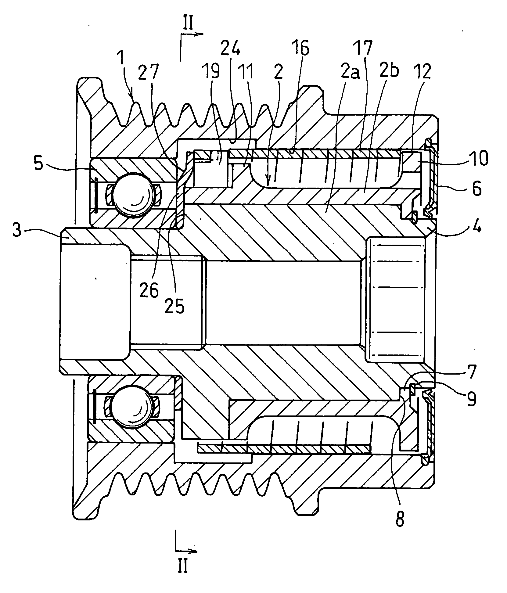
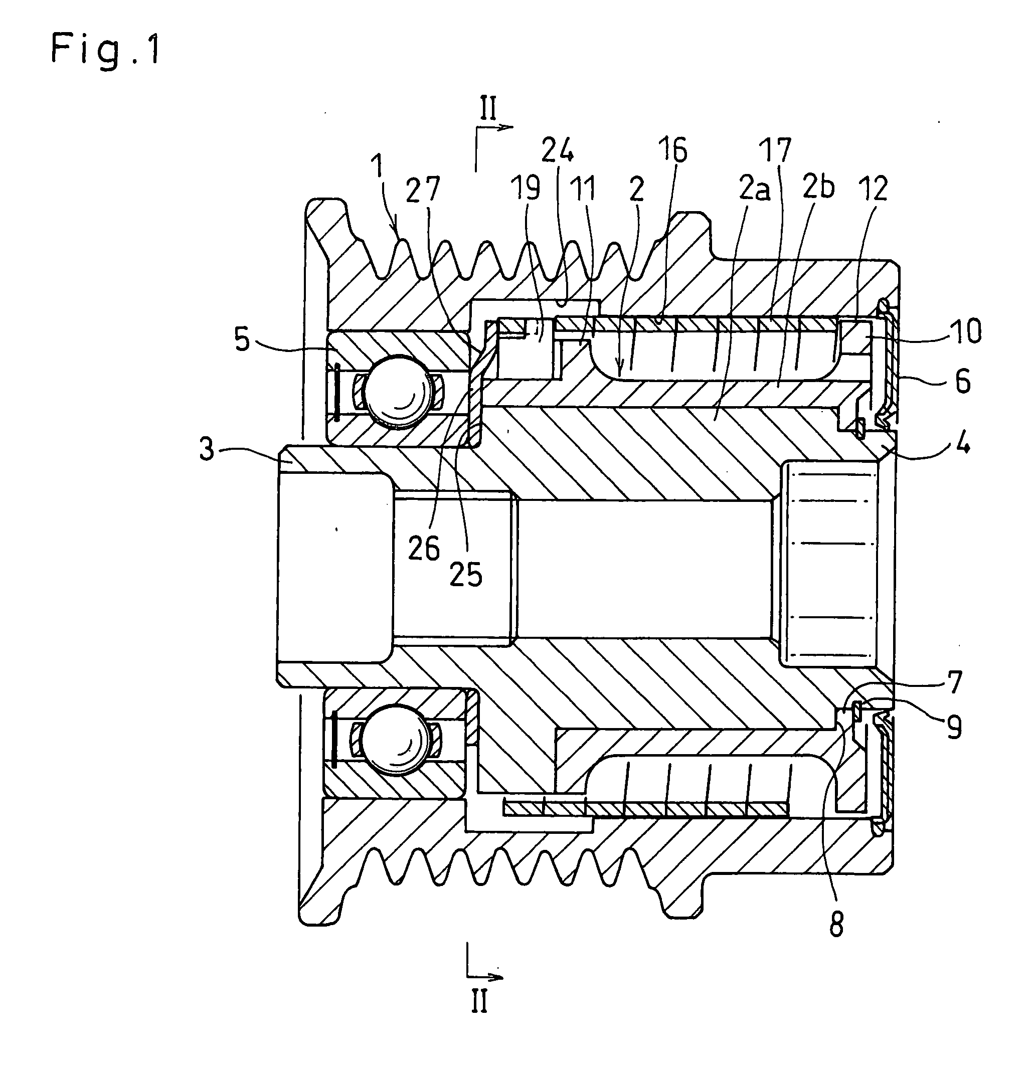
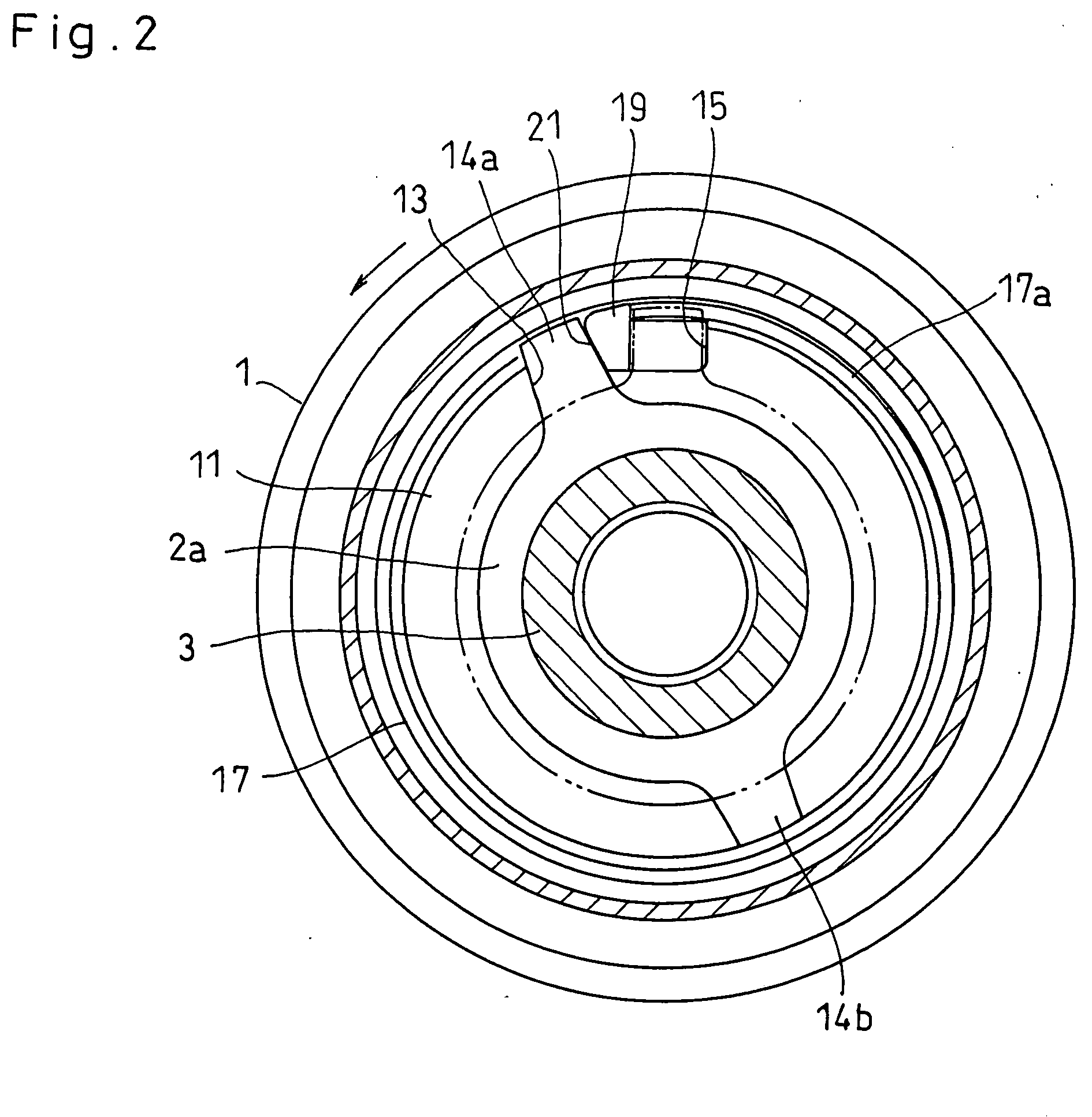
[0063]The embodiments of the present invention are described below with reference to the accompanying drawings. FIGS. 1 to 3 show a spring clutch according to the present invention. As shown in FIG. 1, the spring clutch includes a pulley 1 as an input member, and a pulley hub 2 as an output member mounted in the pulley 1.

[0064]The pulley hub 2 comprises an output shaft 2a made of a metal and a sleeve 2b mounted around the output shaft 2a. The output shaft 2a has an opposed pair of small-diameter portions 3 and 4 at both ends thereof. Between the small-diameter portion 3 at one end of the output shaft 2a and the corresponding end of the pulley 1, a single-seal bearing 5 is mounted to support the pulley 1 and the pulley hub 2 so as to be rotatable relative to each other.

[0065]At the other end of the pulley 1, a seal 6 is mounted between the pulley 1 and the output shaft 2a and has its inner periphery in elastic contact with the outer periphery of the small-diameter portion 4 at the ot...

third embodiment

[0089]FIGS. 6 and 7 show a spring clutch according to this invention. In this embodiment, a pulley 1 as an input member and a pulley hub 2 as an output member are supported by a bearing 5 mounted at one end of the pulley 1 so as to be relatively rotatable. The pulley 1 has an radially inner cylindrical clutch surface 16 which is formed with a large-diameter recess 24 at its end near the bearing 5.

[0090]A clutch spring 17 in the form of a coil spring is mounted in a radially compressed state in the pulley 1 and has a clutch portion 17c at a position opposite to the clutch surface 16 which is in elastic contact with the clutch surface 16. The clutch spring 17 has a damper portion 17d at a position opposite to the large-diameter recess 24. The damper portion 17d has its end portion fitted on a small-diameter spring fitting surface 11a formed on a flange 11 provided at one end of the pulley hub 2 and has its extreme end inserted and engaged in a spiral groove 30 opening to the spring fi...

fifth embodiment

[0108]FIGS. 16 to 18 show a spring clutch according to the invention. In this embodiment, an elastic ring 50 is mounted in place of the cover ring 40 to supplement the spring rigidity of the portion of the clutch spring 17 near the torque transmission end.

[0109]The elastic ring 50 is formed with a cut 52 at a portion of the circumference of a cylindrical member 51. As shown in FIG. 17, between the elastic ring 50 and the large-diameter recess 24, there is formed a gap 5 of such a size that even if the pulley 1 is loaded with the maximum design torque (that is, maximum allowable torque to the spring clutch) and the elastic ring 50 expands, the outer periphery of the elastic ring 50 does not contact the-inner periphery of the large-diameter recess 24.

[0110]As shown in the fifth embodiment, by mounting the elastic ring 50 at the portion of the clutch spring 17 including the torque transmission end, the spring rigidity of this portion of the clutch spring 17 increases. This makes it pos...


PUM


Abstract

A spring clutch is provided which has improved durability by preventing a clutch spring from breaking due to fatigue. A cylindrical clutch spring made from a wire having a square section is mounted between a pulley and a pulley hub mounted in the pulley. An end of the clutch spring is coupled to the pulley hub. A clutch surface is formed on the inner periphery of the pulley and is formed with a large-diameter recess at a position opposite to the end portion of the clutch spring including the torque transmission end. When the pulley rotates in one direction, the clutch spring expands. At this time, the end portion of the clutch spring including the torque transmission end expands in the large-diameter recess, thus relaxing sharp torque produced in the clutch. This prevents local stress concentration on the clutch spring and breakage of the clutch spring and improves the durability of the clutch.

Description

BACKGROUND OF THE INVENTION[0001]The present invention relates to a spring clutch comprising a clutch spring in the form of a coil spring mounted between an input member and an output member for transmitting the rotation of the input member in one direction to the output member and cutting off the transmission of rotation if the rotating speed of the output member exceeds the rotating speed of the input member.[0002]Generally, with an engine accessory driving apparatus for transmitting the rotation of the crankshaft of an engine to rotary shafts of engine accessories through a belt transmission, if the engine is decelerated quickly, a pulley mounted on the rotary shaft of each engine accessory also tends to quickly. Especially in the case of an alternator, because the rotary shaft of the alternator has a large inertia, it cannot decelerate quickly in response to quick deceleration of the engine, so that the pulley mounted on the rotary shaft tends to continue to rotate at a constant...

Claims


Application Information

Patent Timeline
Patent Type & Authority Applications(United States)
IPC IPC(8): F16D41/20F16D13/08
CPCF16D41/206
Inventor SAITO, TAKAHIDENAKAKOJI, MASAFUMIFURUTANI, KATSUMIAKIYOSHI, KOJIMAKINO, TOMOAKI
Owner NTN CORP
Why Eureka
Try Eureka