
Device and Method for Controlling the Positioning of a Stent Graft Fenestration

a technology of fenestration and stent, which is applied in the field of stent graft, can solve the problems of difficult deployment of guidewires and catheters from the stent graft into the branch vessel, and achieve the effect of improving the stability and stability of the stent graft and the branch vessel

Inactive Publication Date: 2007-10-18
MEDTRONIC VASCULAR INC
View PDF7 Cites 133 Cited by
  • Summary
  • Abstract
  • Description
  • Claims
  • Application Information

AI Technical Summary

Benefits of technology

[0005] Various embodiments according to the present invention are directed to apparatus and methods of using an integrated member pre-attached to a flexible, translatable, fenestration of a stent graft that may be used to guide a catheter into engagement with the fenestration to provide control thereof after the stent

Problems solved by technology

Repairing such a vessel without providing blood flow into the branch vessel can cause problems.
One issue that exists in such a procedure is how to accurately position a fenestration in relation to the branch vessel.
If the position of a fenestration is offset with respect to a branch vessel when the stent graft is deployed, it may be difficult to deploy guidewires and catheters from the stent graft into the branch vessel to enable correct positioning of the branch vessel stent graft.

Method used


Image

  • Device and Method for Controlling the Positioning of a Stent Graft Fenestration
  • Device and Method for Controlling the Positioning of a Stent Graft Fenestration
  • Device and Method for Controlling the Positioning of a Stent Graft Fenestration

Examples


Embodiment Construction

[0024] Specific embodiments are now described with reference to the figures, wherein like reference numbers indicate identical or functionally similar elements. The terms “distal” and “proximal” when used in the following description with respect to the catheter are a position or direction relative to the treating clinician. “Distal” or “distally” are a position distant from or in a direction away from the clinician. “Proximal” and “proximally” are a position near or in a direction toward the clinician. The terms “distal” and “proximal” when used for the implanted device are used with respect to the direction of blood flow from the heart, wherein the proximal end denotes the end nearer the heart.

[0025] The following detailed description is merely exemplary in nature. Although the description of embodiments in accordance with the invention are in the context of treatment of blood vessels, such as the renal arteries, the embodiments may also be used in other passageways where it is d...


PUM


Abstract

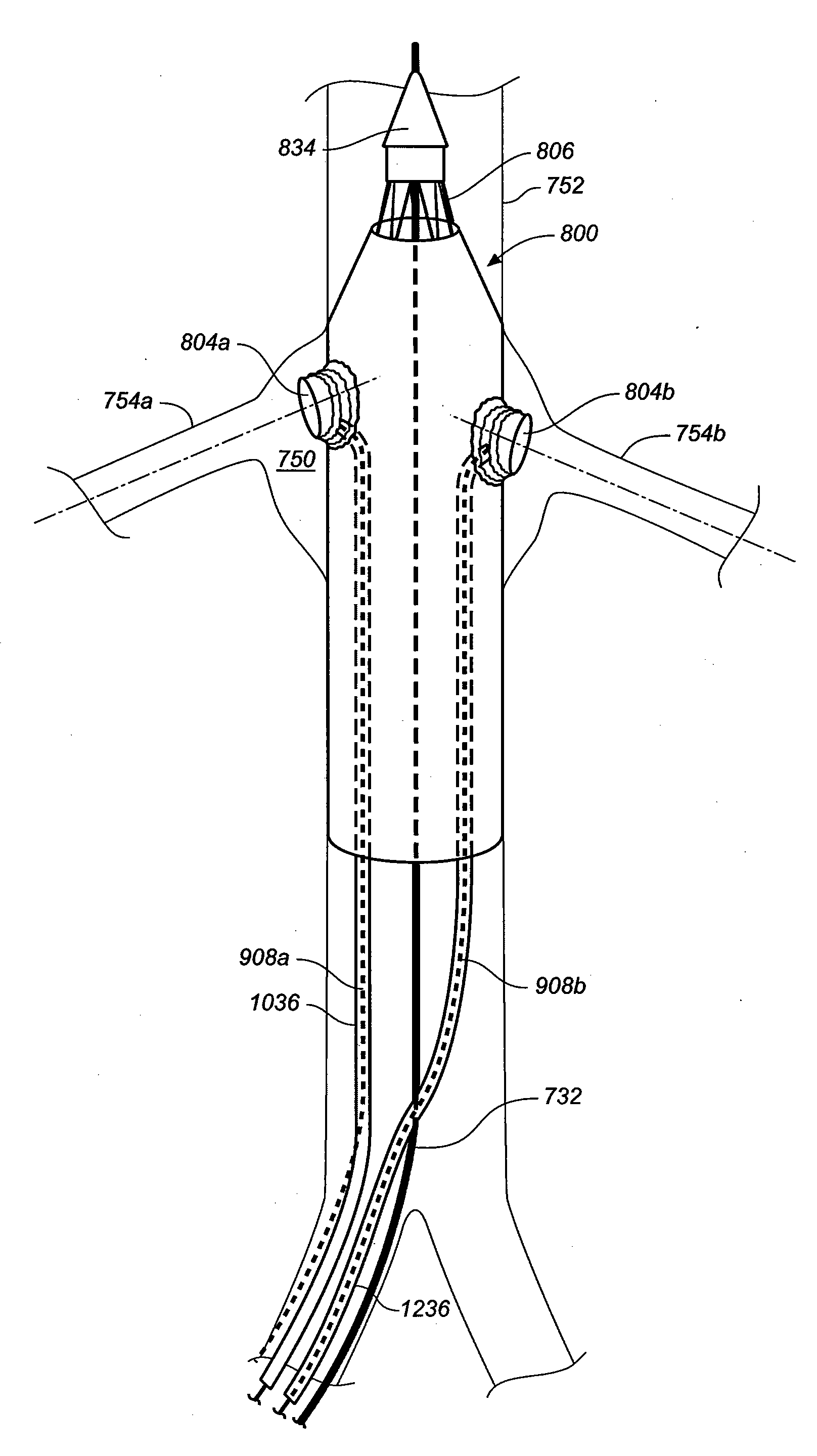
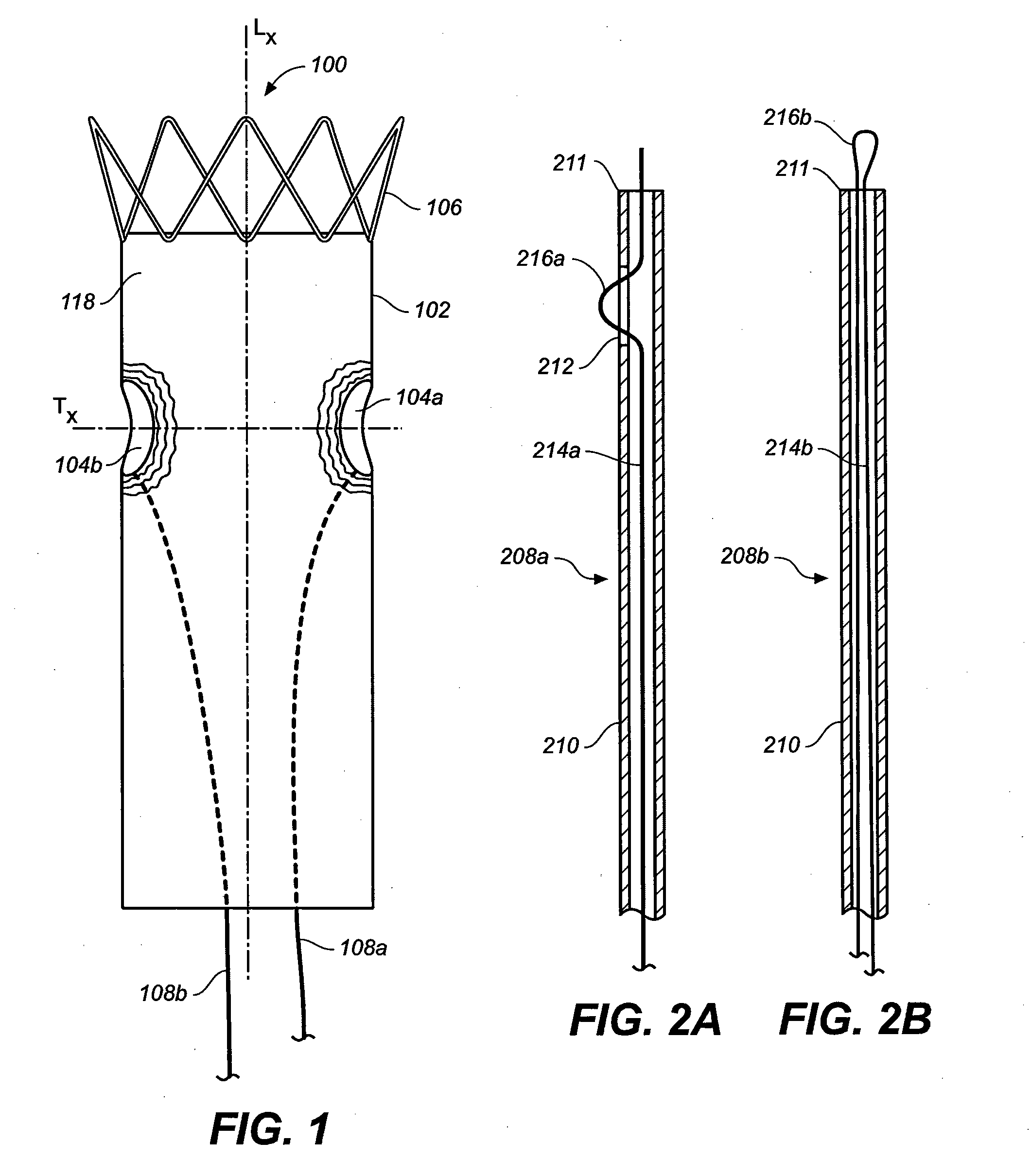
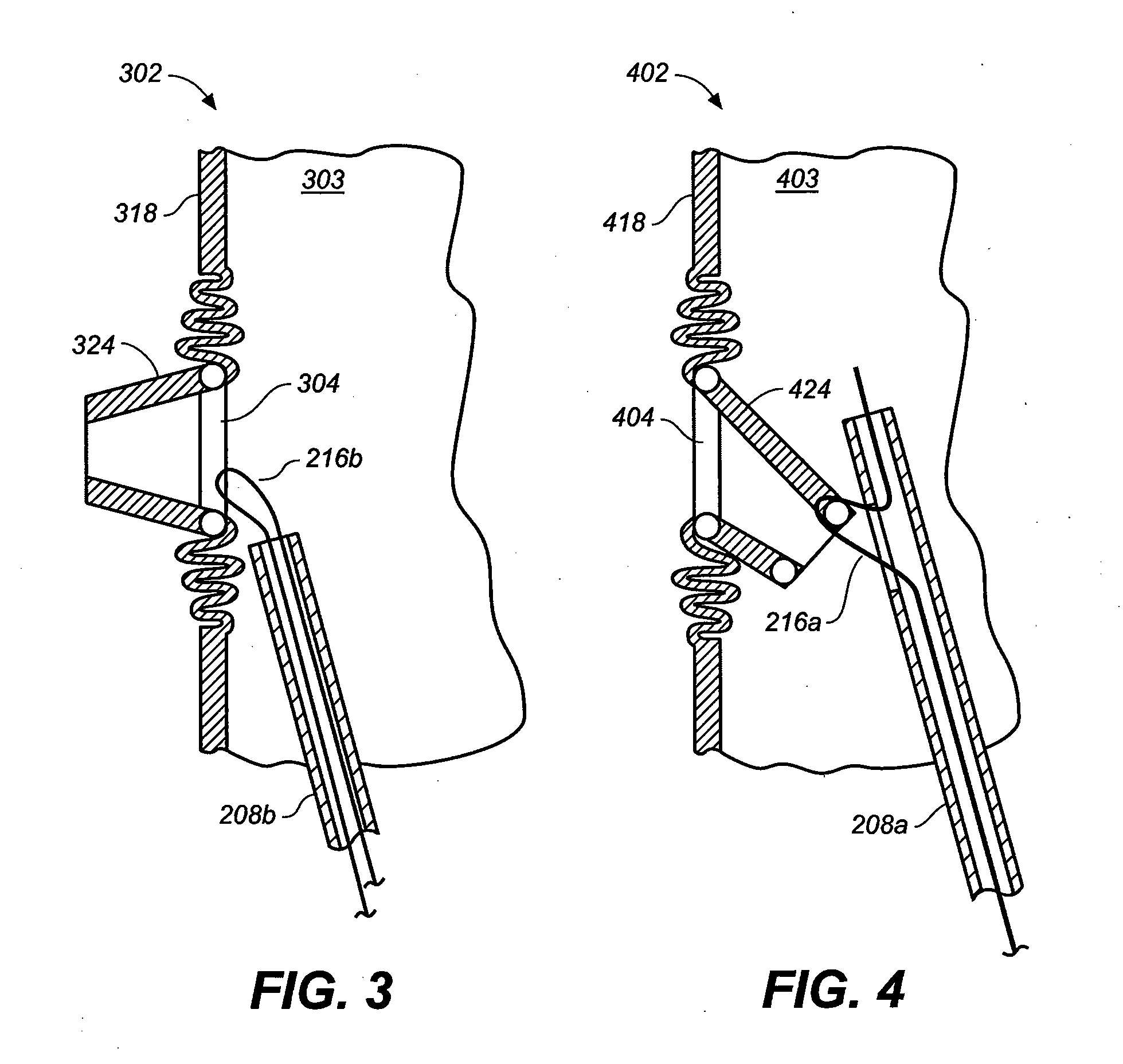
A device and method for controlling the positioning of one or more flexible stent graft fenestrations are disclosed. The stent graft may be for repair of an aneurysm proximate a branch vessel. The stent graft includes a primary graft having an anchoring device, a graft material forming a central lumen and at least one flexible fenestration in a side wall thereof. A fenestration positioning member extends within the stent graft central lumen and has a distal end removably attached to the stent graft proximate the at least one flexible fenestration. The fenestration positioning member may include a tubular member having a wire extending there through, wherein a sidewall of the tubular member includes an aperture through which a loop of the wire extends and removably attaches to the fenestration. Alternatively, the fenestration positioning member may include a tubular member having a suture extending there through, wherein a loop of the suture distally extends from a distal end of the tubular member and is removably attached to the fenestration. The stent graft may include one or more flexible fenestrations, each fenestration having a fenestration positioning member removably attached thereto.

Description

FIELD OF THE INVENTION [0001] The invention relates to a stent graft having at least one fenestration for placement proximate a branch vessel. More particularly, the invention relates to a device and method for controlling the positioning of a stent graft fenestration with respect to the branch vessel. BACKGROUND OF THE INVENTION [0002] Stent grafts are often used for treatment of the vasculature in a body to bypass and repair a defect in the vasculature. For instance, a stent graft may be used to span an abdominal aortic aneurysm. In many cases such damaged or defected portions of the vasculature may include or be proximate to a branch vessel, such as a mesenteric artery or a renal artery. Repairing such a vessel without providing blood flow into the branch vessel can cause problems. As such, a stent graft having a fenestration in a side wall thereof is utilized, wherein the fenestration is positioned to align with the opening, or ostium, of the branch vessel after deployment of th...

Claims


Application Information

Patent Timeline
IPC IPC(8): A61F2/06
CPCA61F2/07A61F2002/061A61F2220/0075A61F2/89A61F2002/075
Inventor GREENAN, TREVOR
Owner MEDTRONIC VASCULAR INC
Learn More