
System and method for heart valve replacement

a heart valve and system technology, applied in the field of heart valve replacements, can solve the problems of invariably taking a long time duration, various bleeding complications, subjected to adverse effects, etc., and achieve the effect of conserving tim

Inactive Publication Date: 2007-10-18
MACHIRAJU VENKAT R
View PDF38 Cites 49 Cited by
  • Summary
  • Abstract
  • Description
  • Claims
  • Application Information

AI Technical Summary

Benefits of technology

"The present invention provides a heart valve replacement system and method that reduces the time a patient is subjected to a heart-lung machine during surgery. This is achieved by using a two-ring system that allows for a faster and more efficient replacement of the heart valve. The first outer anchoring ring is fastened to the patient's heart valve annulus and the second inner valve ring is sutured to the prosthetic valve outside of the patient's body. This system and method enable a reduction of patient machine time, resulting in significant benefits for the patient."

Problems solved by technology

Current surgical heart valve implantation is a highly skilled surgical procedure and invariably takes prolonged time duration.
During this procedure the patient is on cardiopulmonary bypass and is subjected to the adverse effects of such prolonged bypass time.
Presently, during heart valve replacements, trauma to blood on the heart lung machine is known to lead to various bleeding complications and also end organ failure.
In such installations however, perivalvular leaks were reportedly a problem along with heart blocks.
There are examples of heart valve replacement tools and procedures with differing results and practical limitations.
The heart valve stapling arrangements known hitherto have disadvantages in terms of exposing the patient to prolonged durations on the heart-lung machine during the valve replacement.

Method used


Image

  • System and method for heart valve replacement
  • System and method for heart valve replacement
  • System and method for heart valve replacement

Examples


Embodiment Construction

[0023]A detailed description of one or more embodiments of the invention is provided below using the accompanying figures that illustrate by way of example the principles of the invention. While the invention is described in connection with such embodiments, it should be understood that the invention is not limited to any particular embodiment. On the contrary, the scope of the invention is limited only by the claims and the claim-equivalents, noting that the invention encompasses numerous alternatives, modifications and equivalents. For the purpose of example, numerous specific details are set forth in the following description in order to provide a thorough understanding of the present invention.

[0024]The present invention may be practiced using the principles of the invention, without some or all of these specific details. For the purpose of clarity, technical material and information that is known in the technical fields related to the invention have not been described in detail...


PUM


Abstract

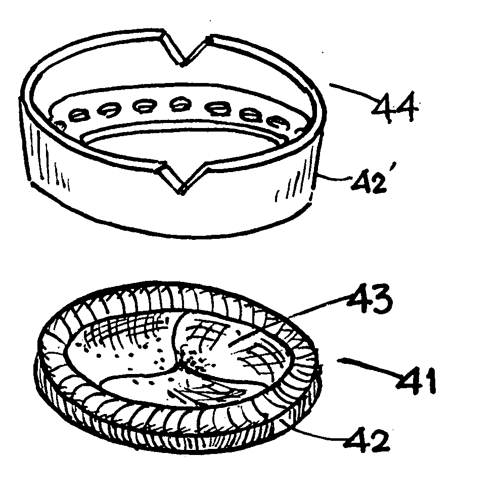
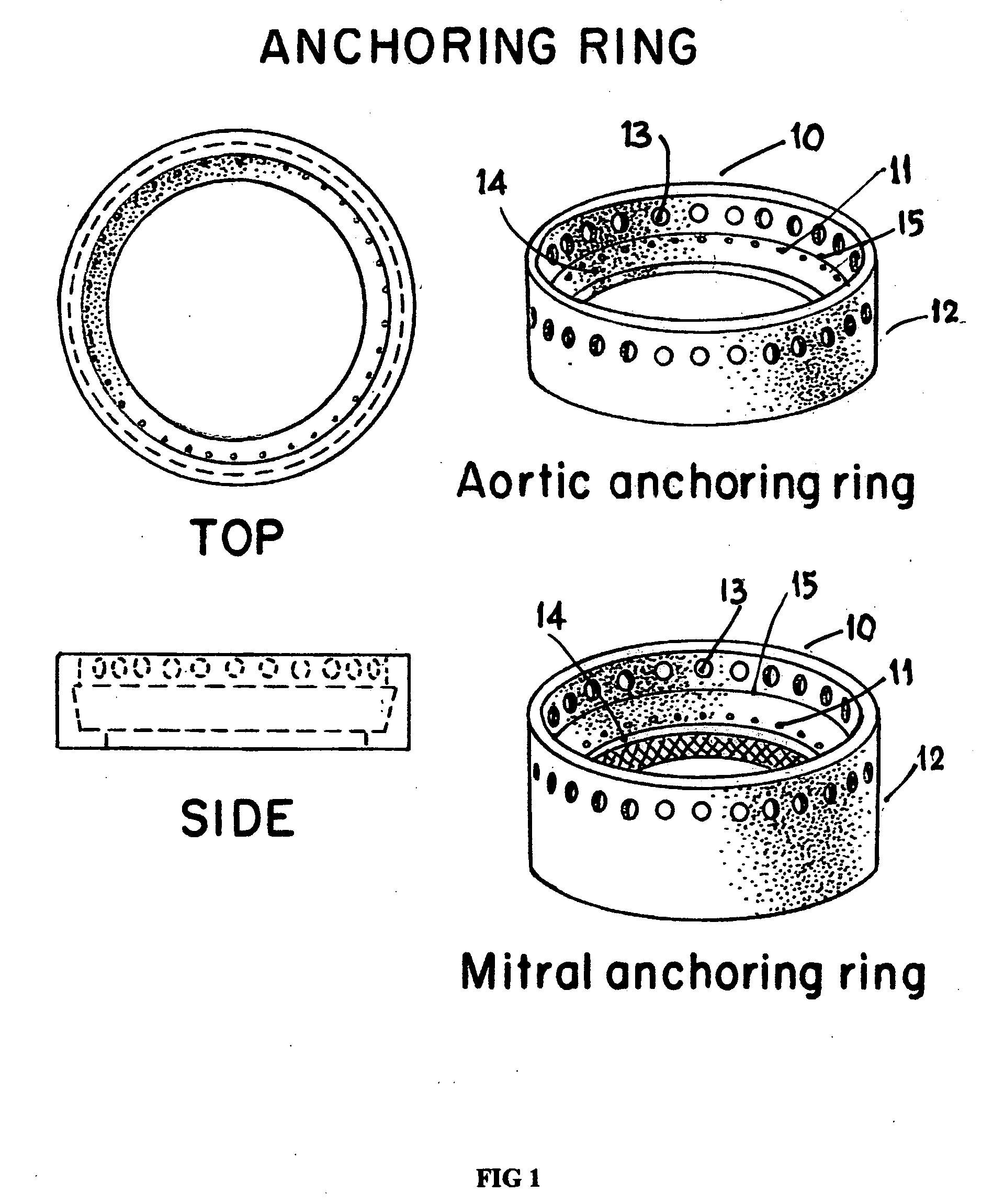
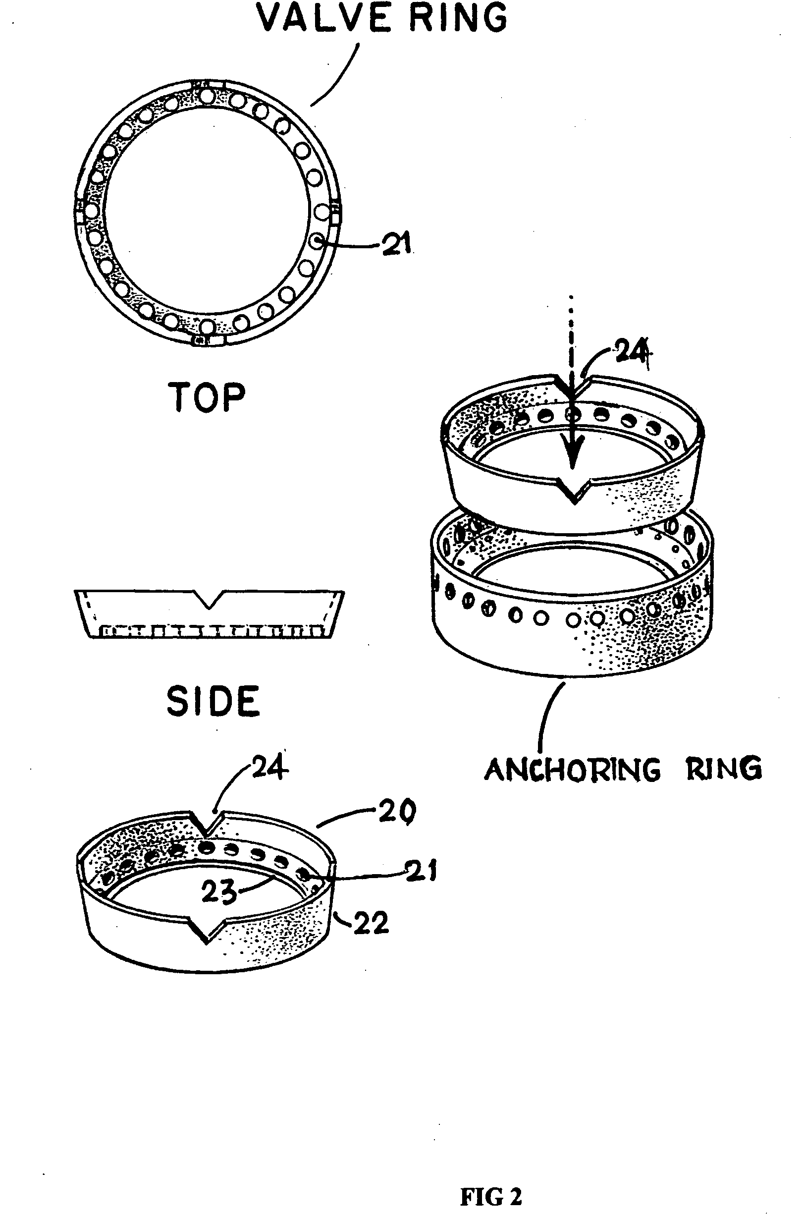
A prosthetic heart valve replacement system and method aim to reduce the time duration of the patient on the heart-lung machine during surgery. In one embodiment, the invention uses a two rings (e.g., of Titanium) comprising a first outer anchoring ring installed in a first step in the patient annulus, e.g., by stapling (e.g., using Nitinol® staples), and a second inner valve ring which has apertures and to which the sewing cuff of prosthetic heart valve (e.g., of Dacron) is sutured around the sewing cuff. The suturing is expediently completed outside of the patient's body, parallel with the stapling of the anchoring ring in the patient annulus. The inner valve ring may have circumferential resiliency. The inner valve ring along with the fastened / sutured prosthetic valve is installed snugly (in a second step) to be captively retained concentrically within the already installed outer anchoring ring, to complete the heart valve replacement.

Description

RELATED APPLICATIONS[0001]Benefit is claimed under 35 U.S.C. 119(e) to U.S. Provisional Application Ser. No. 60 / 792,260, entitled “System and a Method for Heart Valve Replacement” by Venkat R Machiraju, filed on Apr. 14, 2006, which is herein incorporated in its entirety by reference for all purposes.FIELD OF THE INVENTION[0002]This invention relates generally to heart valve replacements, and more particularly to a system and method for surgical heart valve replacement performed with due consideration to the time during which a patient needs to be kept on the heart-lung machine during the valve replacement.BACKGROUND OF THE INVENTION[0003]Heart valve replacement surgeries are very commonly performed all over the world, and presently, at least 90,000 heart valve replacements are performed each year in the United States alone, and more than 500,000 are performed all across the globe. Current surgical heart valve implantation is a highly skilled surgical procedure and invariably takes ...

Claims


Application Information

Patent Timeline
Patent Type & Authority Applications(United States)
IPC IPC(8): A61F2/24
CPCA61F2/2412A61F2/2409
Inventor MACHIRAJU, VENKAT R.
Owner MACHIRAJU VENKAT R
Learn More