Glenoid component with an anatomically optimized keel

a keel and glenoid technology, applied in the field of glenoid components, can solve the problems of relatively invasiveness of studs of this type toward patients, and achieve the effect of superior mechanical strength and stability

Active Publication Date: 2007-10-18
TORNIER SA SAINT ISMIER
View PDF99 Cites 80 Cited by
  • Summary
  • Abstract
  • Description
  • Claims
  • Application Information

AI Technical Summary

Benefits of technology

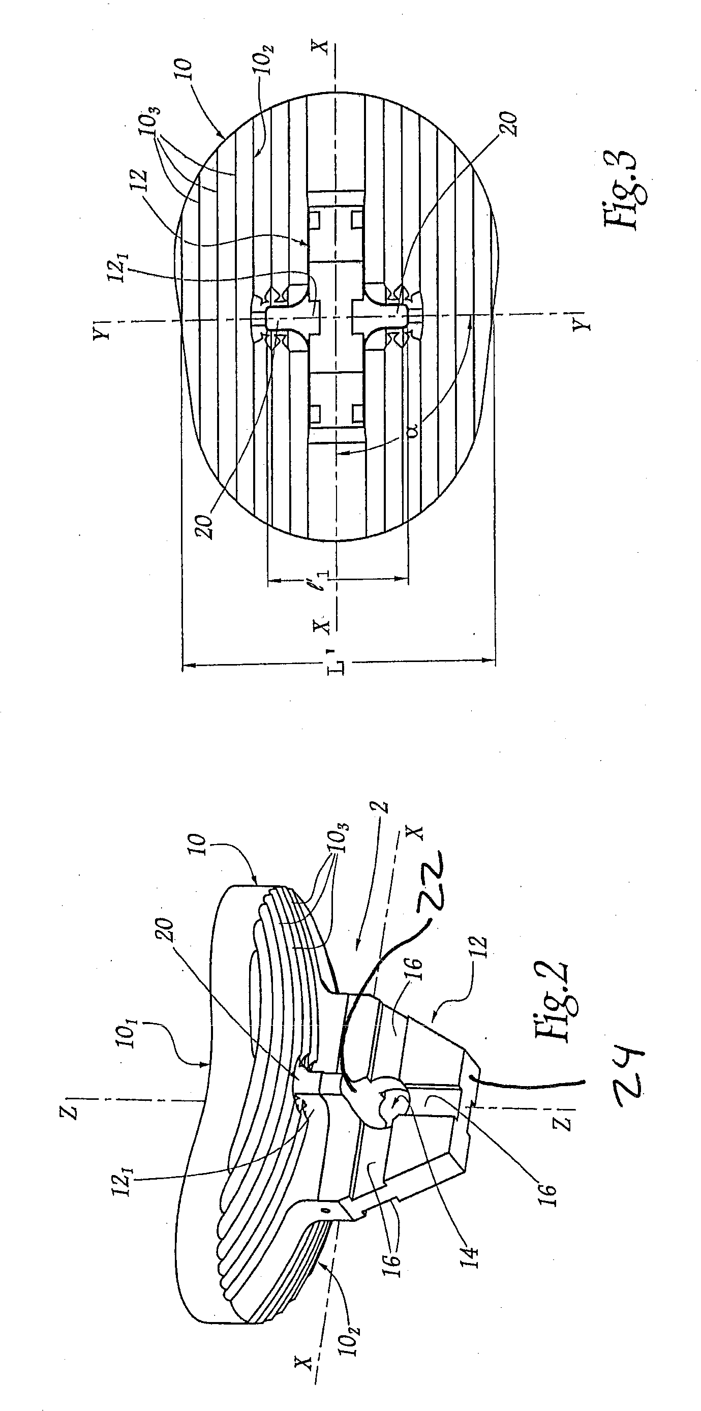
[0008]The various embodiments disclosed herein are directed to a glenoid component for a shoulder prosthesis adapted to be mounted in a glenoid cavity of a shoulder. An elongated keel adapted to engage with the glenoid cavity is attached to the internal surface of the base. The keel extends along a longitudinal axis of the base. The keel includes various configurations of transverse members extending away from the longitudinal axis. The surgeon selects a glenoid component with a keel and transverse member configuration that is anatomically optimized for the patient. Such glenoid components properly optimized for the patient provide mechanical strength and stability superior to prior art devices. The glenoid components disclosed herein are particularly well suited for use in an anatomical total shoulder prosthesis, but many are also suited to partial shoulder prostheses and reverse shoulder prostheses.
[0009]Optimizing the glenoid component for the patient's anatomy has the advantage of minimizing rocking of the glenoid component and reduces loosening of the glenoid component from the glenoid cavity. In addition, the keel and transverse members increase the rigidity of the base of the glenoid component. This structural advantage allows micro-movements to be reduced, owing to the improvement in the primary grip of the entire component. Finally, transverse members anatomically optimized resist shearing forces applied to the glenoid component better than conventional glenoid components.

Problems solved by technology

A stud of this type is relatively invasive toward the patient.
Its use necessitates the removal of a significant portion of the patient's bone stock, which is detrimental in particular when refitting the implant.
However, these various plates for fixing the component in the glenoid cavity are not anatomical since their dimensions are identical to those of the base and, consequently, they are capable of leading to at least partial destruction of the glenoid cavity.

Method used


Image

  • Glenoid component with an anatomically optimized keel
  • Glenoid component with an anatomically optimized keel
  • Glenoid component with an anatomically optimized keel

Examples


Embodiment Construction

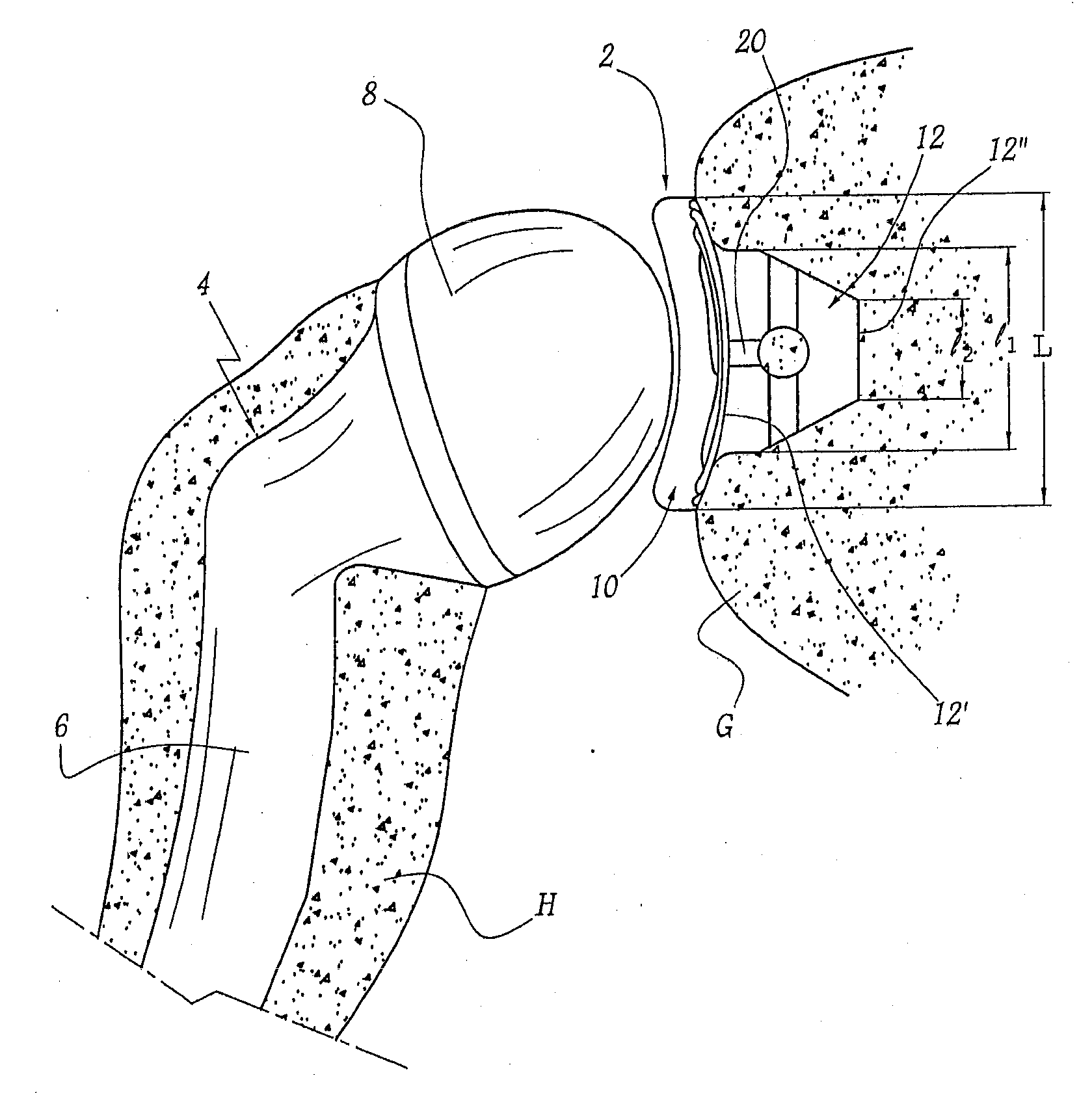
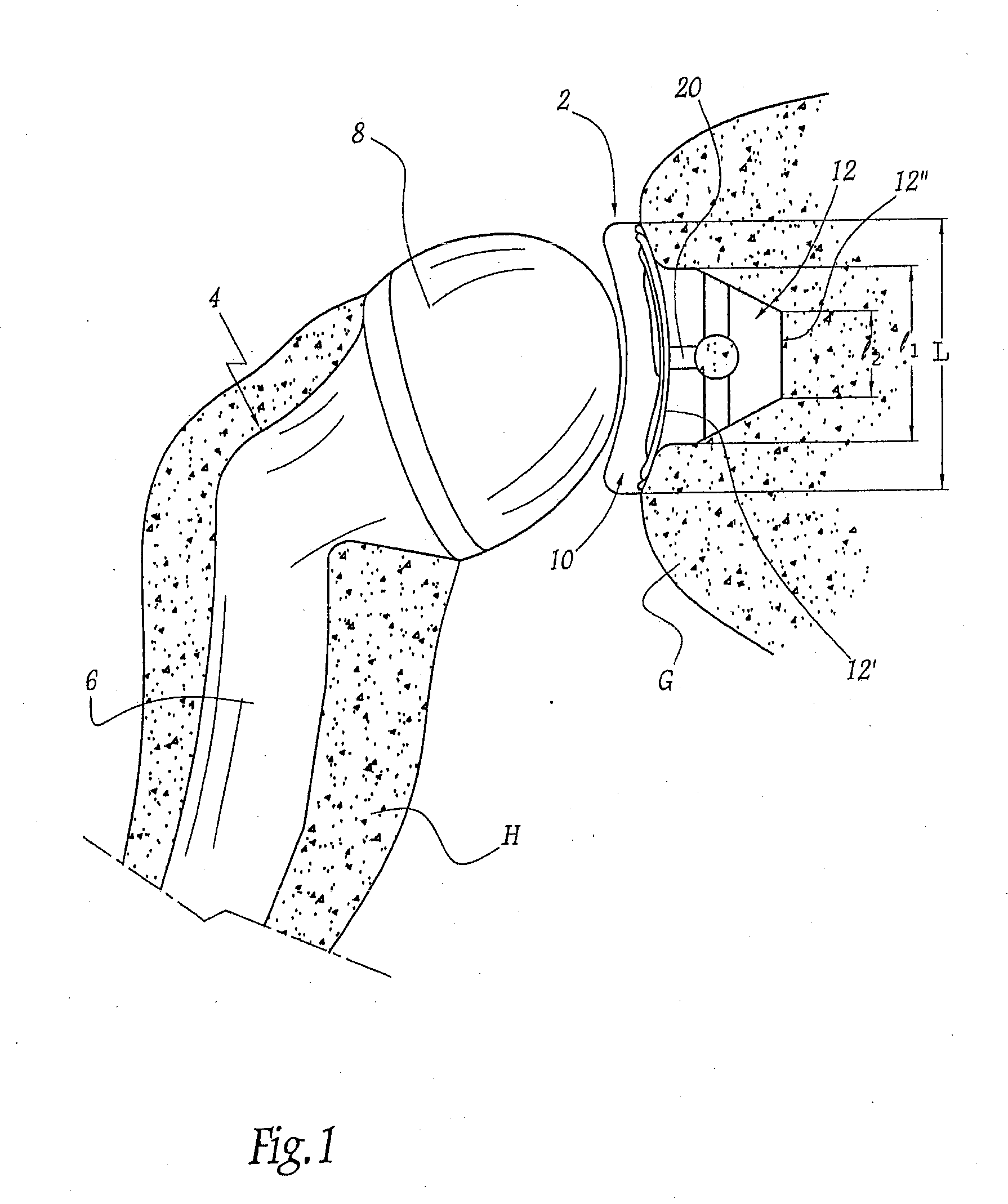
[0024]The total shoulder prosthesis shown in FIG. 1 includes a glenoid component 2 integrally connected to the glenoid cavity G of a shoulder as well as a humeral component 4 integrally connected to the corresponding humerus H. This humeral component 4 includes a stem 6 intended to be fixed in the medullary canal of the humerus H, as well as a hemispherical head 8 including a convex surface.

[0025]The glenoid component 2 includes a base 10 having with an external surface or articular surface 101 opposite the glenoid cavity. In the illustrated embodiment, the external surface 101, includes a concave profile that is intended to cooperate in the anatomical manner with the head 8 of the humeral component 4. The glenoid component 2 can be made of metal, plastics material, ceramic, or composites thereof, or of any other suitable biocompatible material.

[0026]Internal surface 102 of the base 10 rests against the glenoid cavity G of the shoulder. For this purpose, this internal surface 102 is...


PUM


Abstract

A glenoid component for a shoulder prosthesis adapted to be mounted in a glenoid cavity of a shoulder. An elongated keel adapted to engage with the glenoid cavity is attached to the internal surface of the base. The keel extends along a longitudinal axis of the base. The keel includes various configurations of transverse members extending away from the longitudinal axis. The surgeon selects a glenoid component with a keel and transverse member configuration that is anatomically optimized for the patient. Glenoid components properly optimized provide mechanical strength and stability superior to prior art devices. The glenoid components disclosed herein are particularly well suited for use in an anatomical total shoulder prosthesis, but may are also suited to partial shoulder prostheses and reverse shoulder prostheses.

Description

CROSS REFERENCE TO RELATED APPLICATIONS[0001]The present application claims priority to French application No. 0603291 filed on Apr. 13, 2006.FIELD OF THE INVENTION[0002]The present invention relates to a glenoid component with an anatomically optimized keeled for use in total or partial shoulder prosthesis, and to a set of such glenoid components.BACKGROUND OF THE INVENTION[0003]In the field of shoulder prostheses it is known, for example from U.S. Publication No. 2005 / 0049709 (based on FR-A-2 859 099), to use a glenoid component that includes a base capable of resting against the patient's glenoid cavity. The base is combined with a fixing member intended to penetrate deeply into this glenoid cavity in order to connect it securely to the aforementioned component.[0004]U.S. Publication No. 2005 / 0049709 teaches a fixing member is in the form of a keel that includes a main longitudinal axis. The base has a concave surface opposite the keel that is capable of cooperating with a totall...

Claims


Application Information

Patent Timeline
Patent Type & Authority Applications(United States)
IPC IPC(8): A61F2/40
CPCA61F2/4081A61F2002/30125A61F2002/30163A61F2002/30245A61F2002/30604A61F2002/30607A61F2250/0062A61F2002/30879A61F2002/30884A61F2002/30902A61F2230/0008A61F2230/0028A61F2230/0071A61F2002/3082A61F2002/30179
Inventor FERRAND, LUCILEFERRARI, IRENERATRON, YVES-ALAIN
Owner TORNIER SA SAINT ISMIER
Why Eureka
Try Eureka