Side locking insert and material removal tool with same

a side locking and insert technology, applied in the field of indexable inserts, can solve the problems of reducing insert performance such as strength, reducing the cross section of inserts, and limited insert density on milling tools

Active Publication Date: 2007-10-25
SANDVIK TRIANGLE
View PDF31 Cites 58 Cited by
  • Summary
  • Abstract
  • Description
  • Claims
  • Application Information

AI Technical Summary

Problems solved by technology

However, the density of inserts on the milling tool is limited because of the clearance required when taping the lock screw hole in the insert seating surface, and by the use of wedges and or clamps.
In addition, the hole in the insert itself reduces the cross section of the insert, which can reduce insert performance such as strength, in particular for ceramic inserts such as silicon nitride (SiNi) inserts.
However, the chip room for this insert and tool may not be adequate and may foul the tool during operation.

Method used


Image

  • Side locking insert and material removal tool with same
  • Side locking insert and material removal tool with same
  • Side locking insert and material removal tool with same

Examples


Embodiment Construction

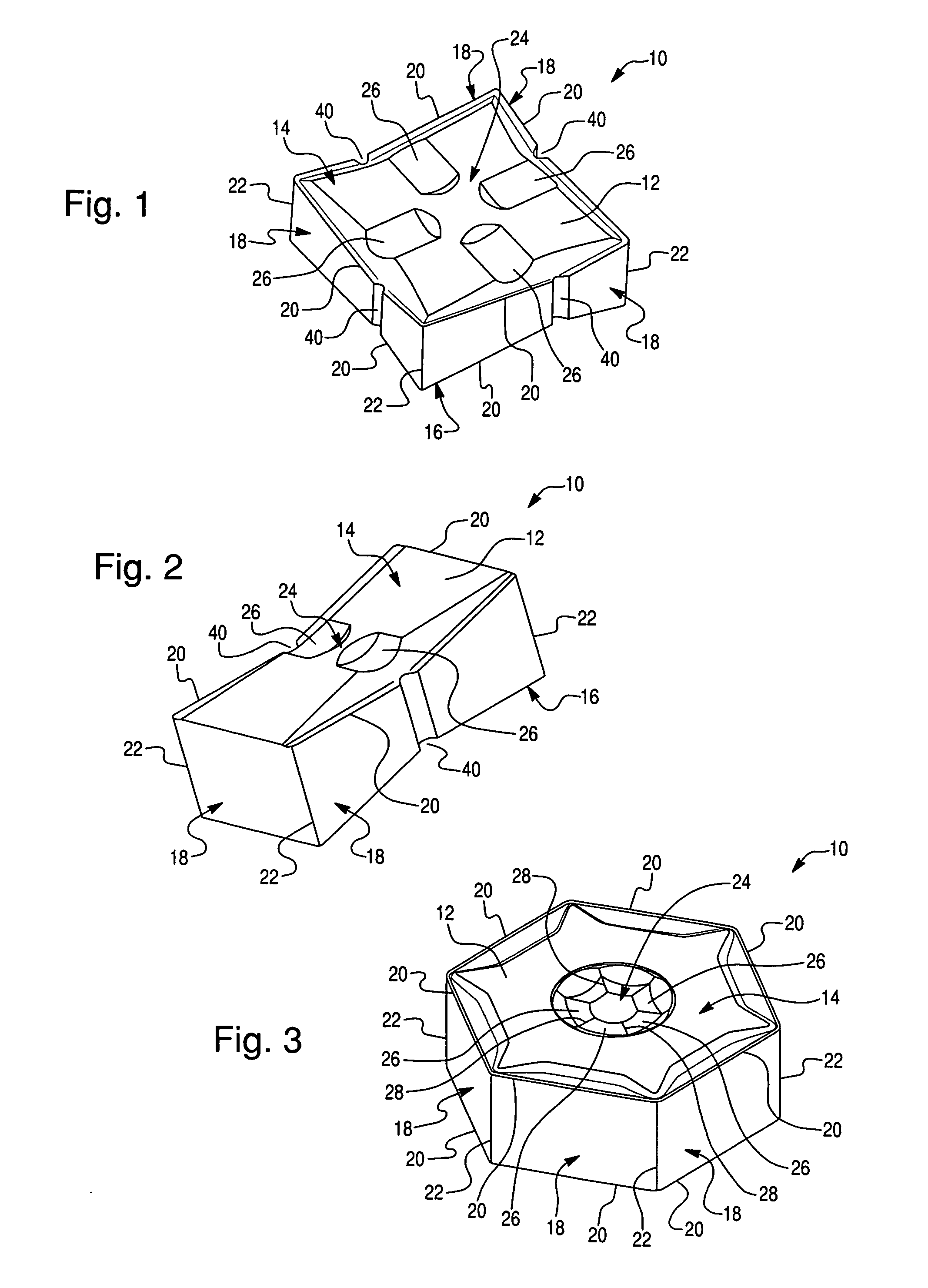
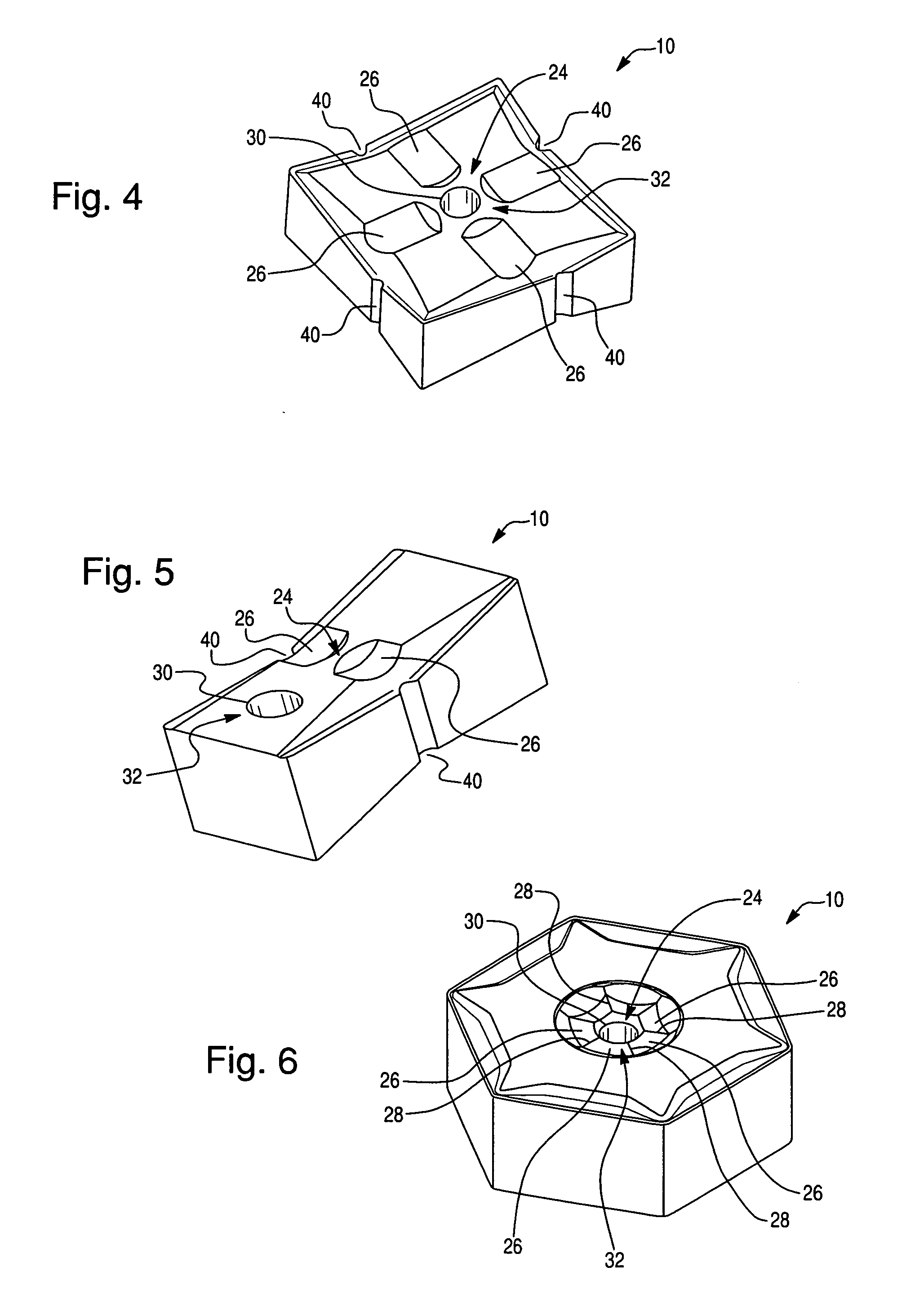
[0020] Indexable inserts of interest herein have front and back surfaces of polygonal shape joined by side edges. At least portions of the intersections of the side edge surfaces with the polygonal surfaces define line edges of the insert and at least portions of the intersections of sequential side edge surfaces define corner edges of the insert. Line edges may be linear or non-linear, as known in the art; corner edges may be round, truncated or other geometries, as known in the art. In general, machining operations are performed so that cutting occurs at an insert corner formed by intersections of corner edges at corners of the polygonal surface, or are performed so that cutting, e.g., milling, occurs at line edges of the insert. In each case, the insert can be traversed along a workpiece surface as the workpiece rotates or the insert can be stationary as the workpiece is rotated and translated. Other combinations of relative motion between the indexable insert and the workpiece c...


PUM

PropertyMeasurementUnit
diameteraaaaaaaaaa
diameteraaaaaaaaaa
diameteraaaaaaaaaa

Abstract

An indexable insert has one or more recesses formed in a frontside or backside surface which receives a surface of the head of a locking screw. When mounted, the insert is forced against respective support surfaces of an insert pocket. The locking screw is threaded into a counterbored tap hole to engage the insert and provide side locating forces and clamping forces to secure the indexable insert in the insert pocket. More particularly, the indexable insert has a shaped surface recess that mates to a complimentarily-shaped surface on the head of a locking screw and secures the indexable insert in multiple dimensions to a seating surface. A material removal tool and a method of mounting the indexable insert are also disclosed.

Description

FIELD [0001] The present disclosure relates to an indexable insert and associated material removal tools. More particularly, the present disclosure relates to an indexable insert, such as a milling insert, a turning insert, a boring insert, a grooving insert or a parting insert, of any shape and either positive or negative, that can be secured to a tool and a method of securing the insert to the tool. BACKGROUND [0002] In the discussion of the background that follows, reference is made to certain structures and / or methods. However, the following references should not be construed as an admission that these structures and / or methods constitute prior art. Applicant expressly reserves the right to demonstrate that such structures and / or methods do not qualify as prior art. [0003] Known tools comprising replaceable inserts use various means for mounting the inserts to the tool body. Some known inserts are mounted with a locking screw passed through the center of the insert and secured i...

Claims


Application Information

Patent Timeline
Patent Type & Authority Applications(United States)
IPC IPC(8): B23P15/28
CPCB23C5/202B23C5/2243B23C2200/086B23C2210/165Y10T407/1924Y10T407/1942Y10T29/49826Y10T407/2202Y10T407/22Y10T407/2272Y10T407/1934Y10T407/23Y10T407/192Y10T407/2206
Inventor NOGGLE, KENNETH G.
Owner SANDVIK TRIANGLE
Why Eureka
Try Eureka