Flexible interlocking wall system

Inactive Publication Date: 2007-10-25
CERRATO DOMINIC
View PDF0 Cites 53 Cited by
  • Summary
  • Abstract
  • Description
  • Claims
  • Application Information

AI Technical Summary

Benefits of technology

[0010] Accordingly it is an object of the present invention to provide an improved masonry walls system that does not require skilled labor to assemble.
[0012] It is a further object of the present invention to provide an improved masonry wall system that is capable of rapid, on-site assembly.

Problems solved by technology

Although this type of free-standing masonry wall has been used successfully in residential, commercial and industrial construction, it possesses a considerable number of drawbacks.
These include: the necessity of skilled labor for assembly (not handyman friendly), the requirement of mortar as a binding agent between each of the components, the considerable time demanded for construction, the inability to disassemble components and reuse if desired, the incapacity to absorb external pressure changes (such as settling, hydrostatic pressure and seismic disturbances) without significant deterioration to the structural integrity.
Although the use of interlocking male and female dovetails provide a positive lock and represent a significant improvement over similar tongue and grove construction, all of the dovetails used in this conventional art embody a critical disadvantage in terms of assembly.
Despite a long-felt but unresolved need for handyman friendly construction material, this frequent assembly problem, along with the various proprietary components, kept assembly to skilled professionals.
While much of the conventional art, to a certain degree, overcomes some of the difficulties associated with the requirement of mortar, and the inability to disassemble, none provide for the capacity to automatically absorb external pressure changes without significant deterioration in structural integrity.
Unfortunately, this move to steel reinforcement as a means to counter external pressure meant the loss of many of the gains achieved by much of the conventional art.
A wall bound as a sold mass is unable to accommodate the dynamic back and forth movement.
Instead, its rigid composition directly transfers the force to the rest of the building (acting as sort of a lever) weakening the integrity of the entire structure until it finally fails.

Method used


Image

  • Flexible interlocking wall system
  • Flexible interlocking wall system
  • Flexible interlocking wall system

Examples


Embodiment Construction

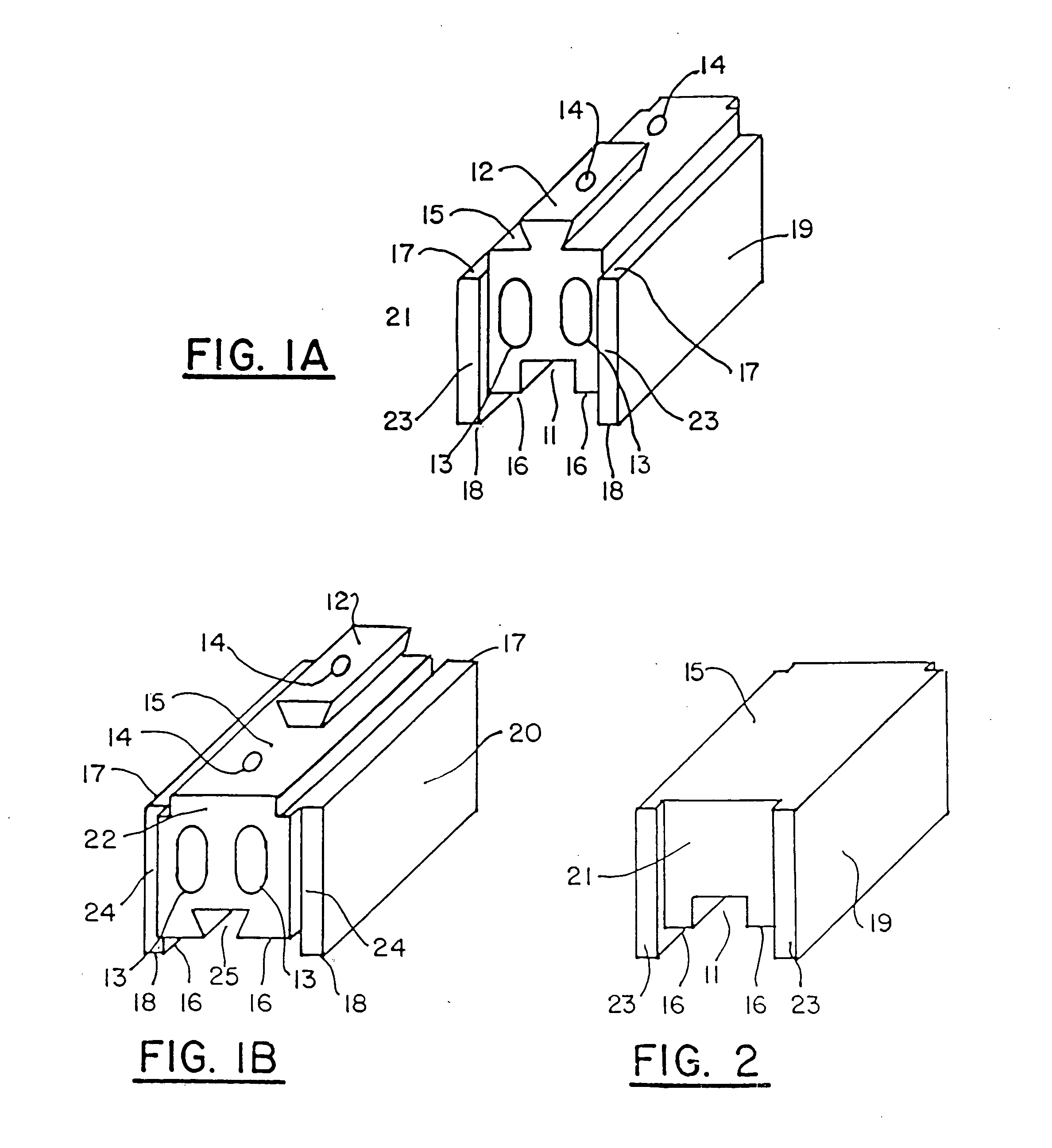
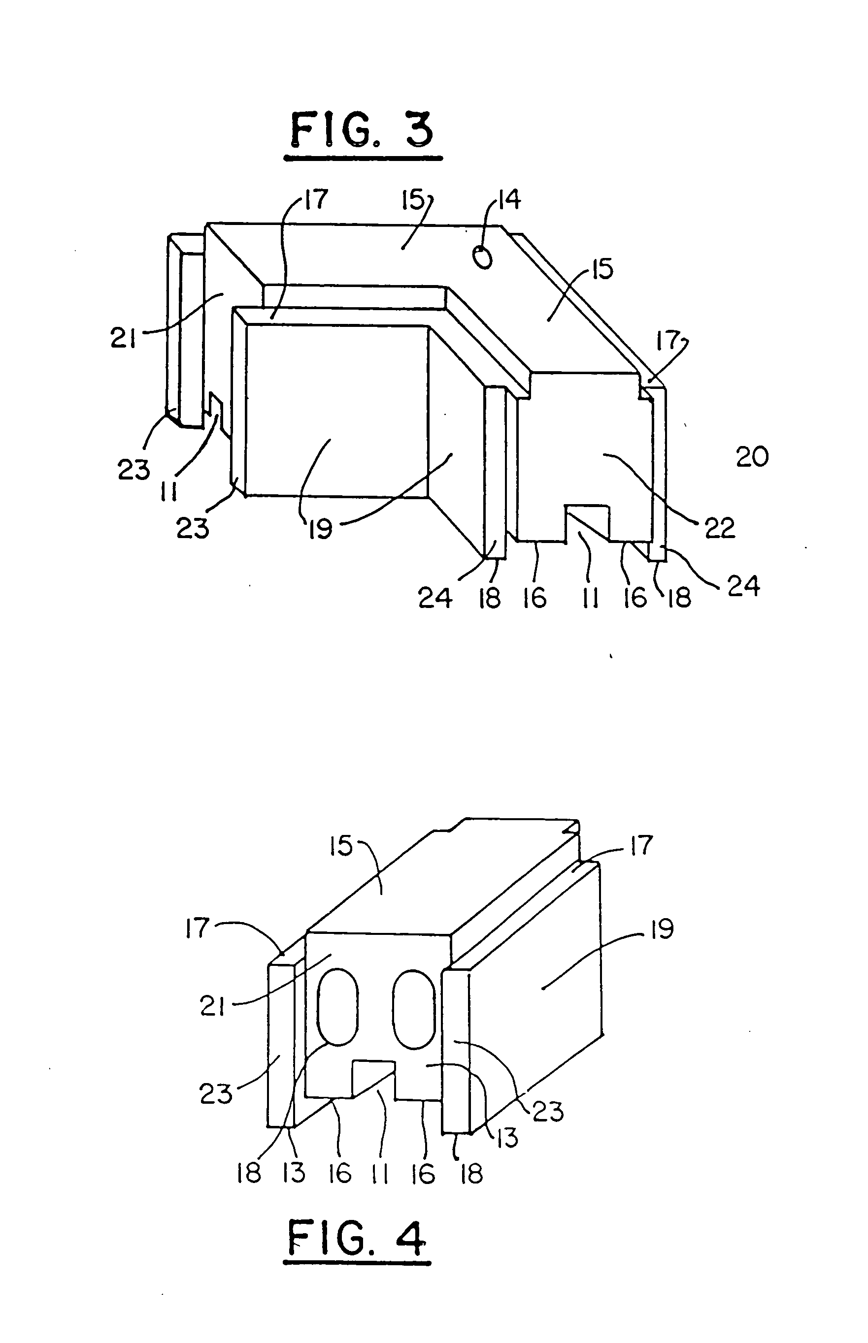
[0107] FIGS. 1(a) and 1(b) depict two perspective views of the main block constituting the present invention. The drawing designation numerals included in FIGS. 1(a) and 1(b) remain the same for all of FIGS. 1(a)-10. For the sake of clarity and efficient consideration of all of the drawings, the legend of the drawing designation numerals is provided below:

11.square receiving slot12.dovetail13.through holes14.stabilizing holes15.upper plane16.lower plane17.upper shoulder18.lower shoulder19.interior sides20.exterior sides21.front plane22.rear plane23.front shoulder24.rear shoulder25.dovetail receiving slot26.corner block27.cynderbrick (main block)28.short block29.footer30.foundation

[0108] The wall system of the present invention is essentially composed of three basic components. These include: a main block, a corner block, and short block. The main block, shown in FIGS. 1(a) (front view) and 1(b) (rear view), is the fundamental component upon which the entire wall system is based. I...


PUM


Abstract

A masonry wall system is disclosed incorporating a plurality of courses of masonry blocks, each block has vertical and horizontal interlocking structures with mating surfaces (11,15,16,17). The main block, has a stabilizing slot. Metal reinforcement tendons are inserted into these stabilizing holes (14) at predetermined intervals and connected to the wall at the top and bottom. Corner blocks (26) are employed to connect the walls at right angles and are used in alternating configurations to staggered the vertical joints from course to course. This is also done with the main blocks. The predetermined tolerances between the masonry components and the reenforcing tendons permit the wall to have a fluid property. Forces such as settling, hydrostatic pressure and seismic disturbances are then automatically absorbed and systematically distributed across the entire wall. When all of the masonry components reach the end of their tolerance, the wall locks up as a solid interconnected mass. The force is then passed on to the stabilizing tendons which now act to stabilize the wall against further movement. The movement of the wall can be adjusted after assembly of this wall by applying increased tension to the tendons.

Description

[0001] This is a continuation-in-part of U.S. patent application Ser. No. 09 / 877,914, filed Jun. 8, 2001, now allowed, which is in turn a continuation-in-part of U.S. patent application Ser. No. 09 / 290,635, filed Apr. 12, 1999, now U.S. Pat. No. 6,244,009, which is in turn a continuation-in-part of U.S. patent application Ser. No. 08 / 925,311, filed Sep. 8, 1997, now U.S. Pat. No. 5,899,040.FIELD OF INVENTION [0002] This present invention relates to an improvement in free-standing mortarless building structures and, in particularly, to a virtually mortarless interconnecting block system with unique dynamic properties. BACKGROUND OF THE INVENTION [0003] Typically speaking, free-standing masonry walls are constructed of concrete blocks (or similar material) in running courses. Each course is placed in such a manner so that the vertical joints are staggered from the previous course. Mortar is used as a binding agent between the courses and between the ends of each of the blocks. Convent...

Claims


Application Information

Patent Timeline
IPC IPC(8): E04B2/08
CPCE04B2/18E04B2002/0254E04B2002/0234E04B2/46
Inventor CERRATO, DOMINIC
Owner CERRATO DOMINIC
Why Eureka
Try Eureka