Passive millimeter wave spectrometer for remote detection of chemical plumes

a technology of millimeter wave spectroscopy and chemical plumes, applied in the field of remote detection, can solve the problems of limited application range of optical systems, superb sensitivity,

Inactive Publication Date: 2007-10-25
UCHICAGO ARGONNE LLC
View PDF12 Cites 9 Cited by
  • Summary
  • Abstract
  • Description
  • Claims
  • Application Information

AI Technical Summary

Problems solved by technology

However, optical systems, which provide superb sensitivity as a direct consequence of high-energy vibrational transitions, are l

Method used


Image

  • Passive millimeter wave spectrometer for remote detection of chemical plumes
  • Passive millimeter wave spectrometer for remote detection of chemical plumes
  • Passive millimeter wave spectrometer for remote detection of chemical plumes

Examples


case 1

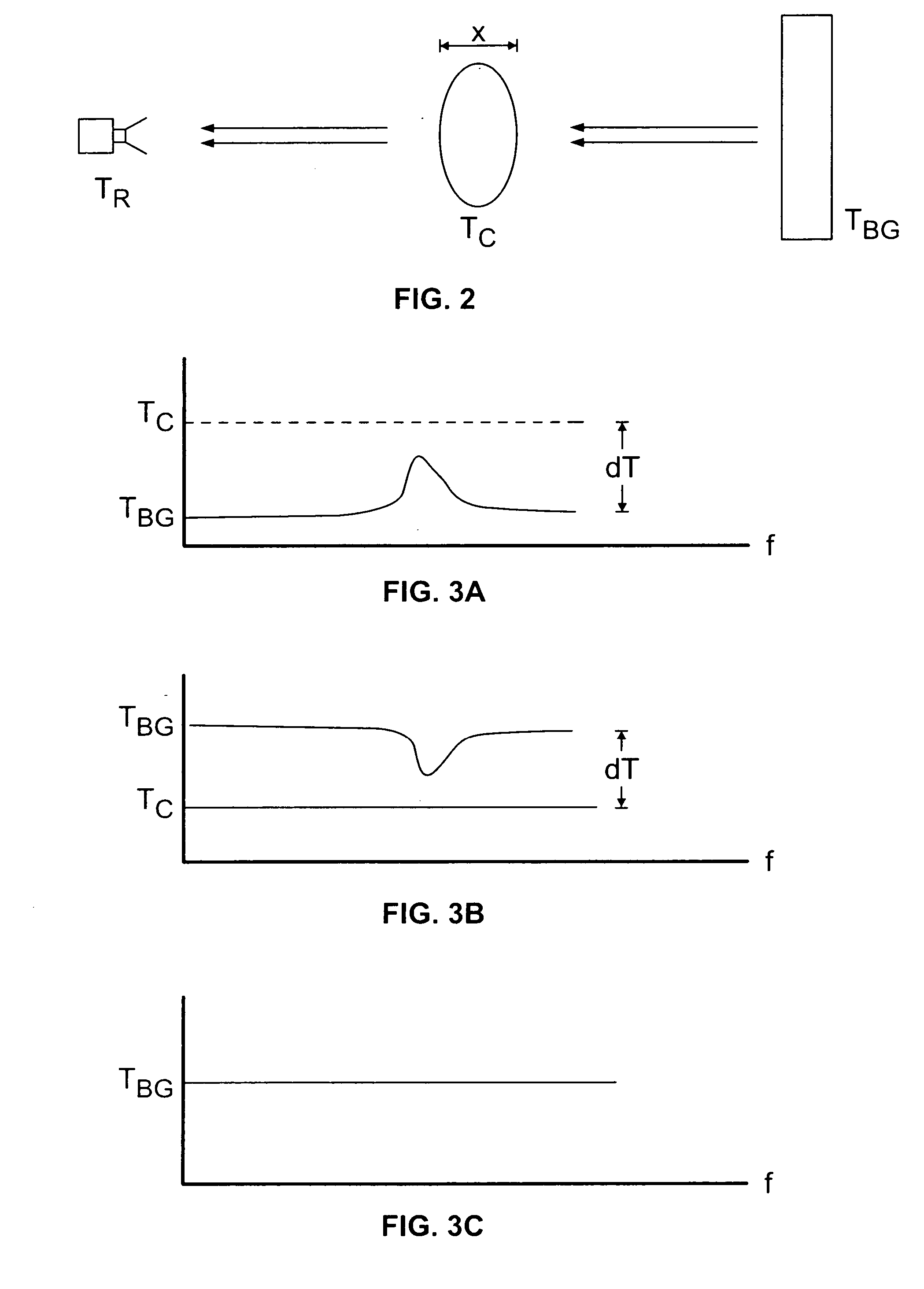
Tbg may be greater than, less than, or equal to Tc: [0028] (Tbgc) The plume emits radiation proportional to its optical depth and dT (FIG. 3A). [0029] Case 2: (Tbg>Tc) The plume absorbs radiation proportional to its optical depth and dT (FIG. 3B). [0030] Case 3: (Tbg=Tc) The plume is transparent (FIG. 3C).

[0031] In addition, the distance of the background will have an impact on the mmW results. FIGS. 4A-b illustrates the effect of a distance, such as mountain background, on the mmW results. In FIG. 4A, θ=84.3; Rc˜1.0 km; Rbg˜2.0 km; Hc: 0.1 km; Dc: 0.01 km; Tc: 288.15 K; {acute over (ε)}BG˜0.7; V%NO: 1. In FIG. 4B, θ=89.4; Rc˜10.0 km; Rbg˜10.5 km; Hc: 0.1 km; Dc: 0.01 km; Tc: 288.15 K; {acute over (ε)}BG˜0.7; V%NO: 1.

[0032] Cloud temperature will also impact the mmW results. FIG. 5A illustrates results where cloud temperature is relatively high (Tc: 350 K) and where θ=85; Rc˜1.15 km; Rbg˜5.7 km; Hc: 0.1 km; Dc: 0.01 km; V%NO: 1. FIG. 5B illustrates results where cloud temperature...


PUM


Abstract

Systems and methods for the passive measurement of spectral lines from the absorption or emission by polar molecules. The system includes mmW front-end assembly, back-end electronics, and data acquisition hardware and software was assembled. The method relates to methods for processing multi-channel radiometric data from passive mmW detection systems.

Description

[0001] The United States Government has rights in this invention pursuant to Contract No. W-31-109-ENG-38 between the United States Government and Argonne National Laboratory.BACKGROUND OF THE INVENTION [0002] The present invention relates generally to the field of remote detection. Specifically, the present invention relates to passive millimeter wave spectroscopy for remote detection. [0003] Remote detection systems have become increasingly important in helping to regulate behavior of individuals and corporations. Remote sensing devices serve a wide range of functions from detecting contamination to determining if a person is carrying contraband. Some situations require that a remote sensing device be able to function over a large distance rather than over a short-range only. [0004] Active and passive spectrometers operating in the optical range have been employed in the past for a variety of environmental monitoring applications. Optical techniques are commonly used for remote se...

Claims


Application Information

Patent Timeline
IPC IPC(8): G01T1/00G01J1/00
CPCG01J3/42G01N21/3563G01N2021/1793G01N21/3581
Inventor GOPALSAMI, NACHAPPABAKHTIARI, SASANRAPTIS, APOSTOLOS C.ELMER, THOMAS W.
Owner UCHICAGO ARGONNE LLC
Why Eureka
Try Eureka