Sheet conveying apparatus, image scanning apparatus, and image forming apparatus

a conveying apparatus and scanning technology, applied in the direction of thin material processing, instruments, article separation, etc., can solve the problems of paper jam failure or conveyance failure, the conveying force of the pair of rollers and the sheet feeding operation cannot be steadily performed. , to achieve the effect of simple and low-cost configuration

Active Publication Date: 2007-10-25
RICOH KK
View PDF26 Cites 23 Cited by
  • Summary
  • Abstract
  • Description
  • Claims
  • Application Information

AI Technical Summary

Benefits of technology

[0031]According to one embodiment of the present invention, a compact-sized, space-saving sheet conveying apparatus capable of conveying various sheet types with a simple and low-cost configuration and enabling a user to make a selection as to performance and cost according to the user's requirements, an image scanning apparatus provided with the sheet conveying apparatus, and an image forming apparatus provided with the sheet conveying apparatus are provided.

Problems solved by technology

However, in the sheet conveying apparatus with the above configuration, the following problem arises when conveying a special type of sheet (P) with high rigidity, such as a cardboard recording paper or an envelope.
As a result, the highly rigid sheet (P) cannot move along the conveying path, causing a paper jam failure or a conveyance failure.
Thus, the sheet feeding operation cannot be steadily performed.
However, when the sheet (P) is bent by the curve fix guiding member, the conveying force of the pair of rollers (2a, 2b) alone is insufficient for conveying the highly rigid sheet (P) to counter to the resistance caused by the bending action.
As a result, the following conveyance failures may be caused.
Specifically, the sheet (P) is caused to move in an oblique manner because the center line of the highly rigid sheet (P) does not match the center line of the conveying path, or a paper jam occurs because the highly rigid sheet (P) becomes caught inside the curve fix guiding member and stops moving.
Therefore, in this sheet feeding device, highly rigid sheets are caused to bend more moderately compared to plain paper sheets.
However, the sheet conveying apparatus disclosed in Patent Document 1 merely provides a fixed member for guiding a conveyed sheet, and thus does not eliminate the speed difference between the conveyed sheet, which is a mobile object, and the fixed guiding member.
Accordingly, regardless of the shape or position of the guiding member, resistance occurs in such a direction to obstruct the sheet from being conveyed, resulting in a conveyance load.
That is, this conventional configuration is insufficient for preventing conveyance failures or paper jams.
Particularly when conveying a highly rigid sheet, such as a cardboard recording paper or an envelope, conveyance failures and paper jams frequently occur and flipping noises made by the trailing edge of the sheet become considerably large.
Accordingly, similar to the above, this conventional technology does not eliminate the relative speed difference between the sheet and the reverse guiding member when changing the direction of / guiding the sheet, thus generating a conveyance load.
Particularly when conveying a highly rigid sheet, such as a cardboard recording paper or an envelope, conveyance failures and paper jams frequently occur and flipping noises made by the trailing edge of the sheet become considerably large.
Particularly when conveying a highly rigid sheet, such as a cardboard recording paper or an envelope, conveyance failures and paper jams frequently occur.
However, there are no measures provided for reducing the conveyance load before and after the sheet is supported by the internal rollers, i.e., when the sheet is in contact with the conveying path outside the direction changing section.
Furthermore, nothing is particularly mentioned about behaviors of the leading edge and the trailing edge of the sheet while being conveyed.
Particularly when conveying a highly rigid sheet, such as a cardboard recording paper or an envelope, conveyance failures and paper jams frequently occur and flipping noises made by the trailing edge of the sheet become considerably large.

Method used


Image

  • Sheet conveying apparatus, image scanning apparatus, and image forming apparatus
  • Sheet conveying apparatus, image scanning apparatus, and image forming apparatus
  • Sheet conveying apparatus, image scanning apparatus, and image forming apparatus

Examples


first embodiment

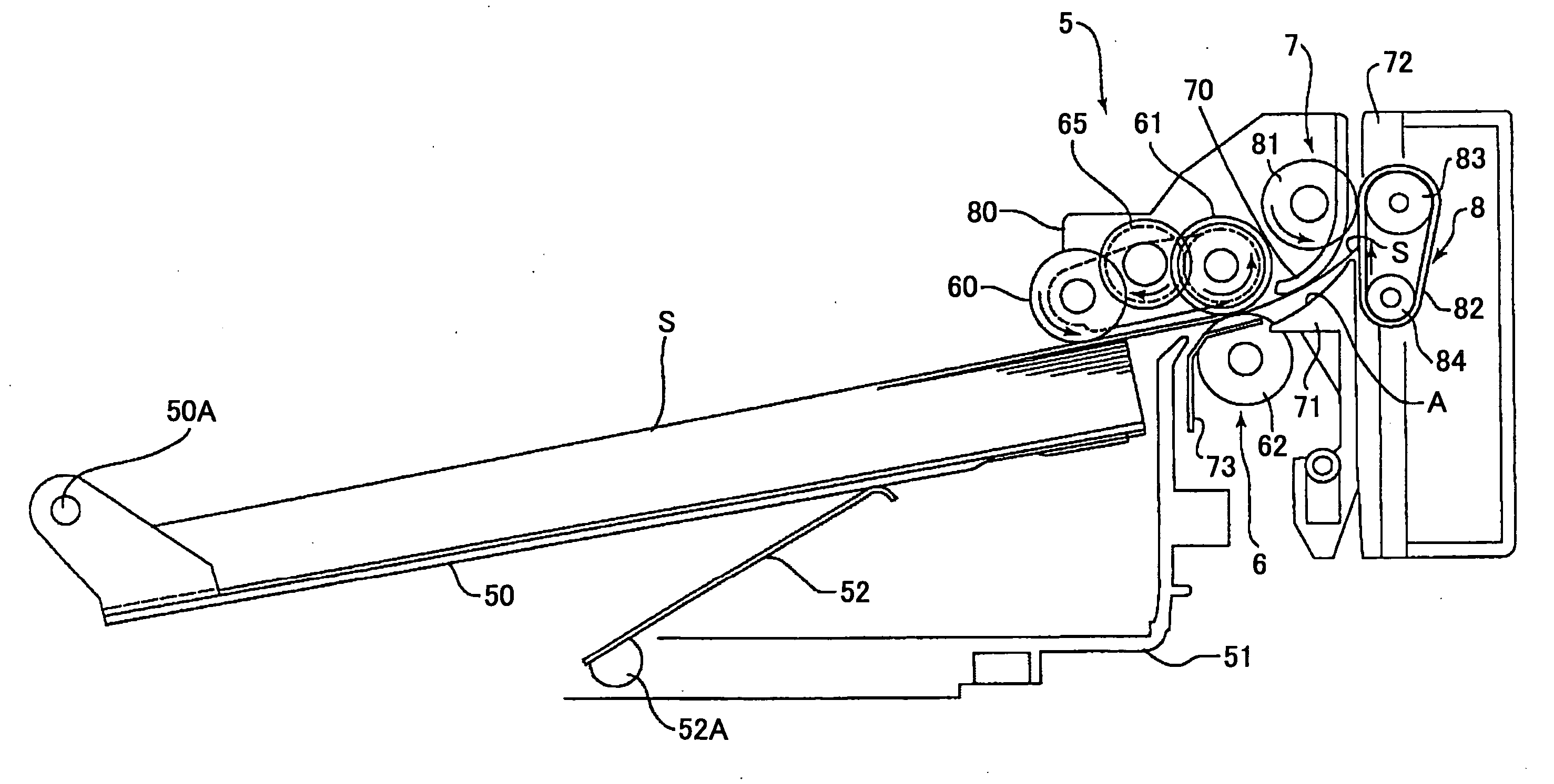
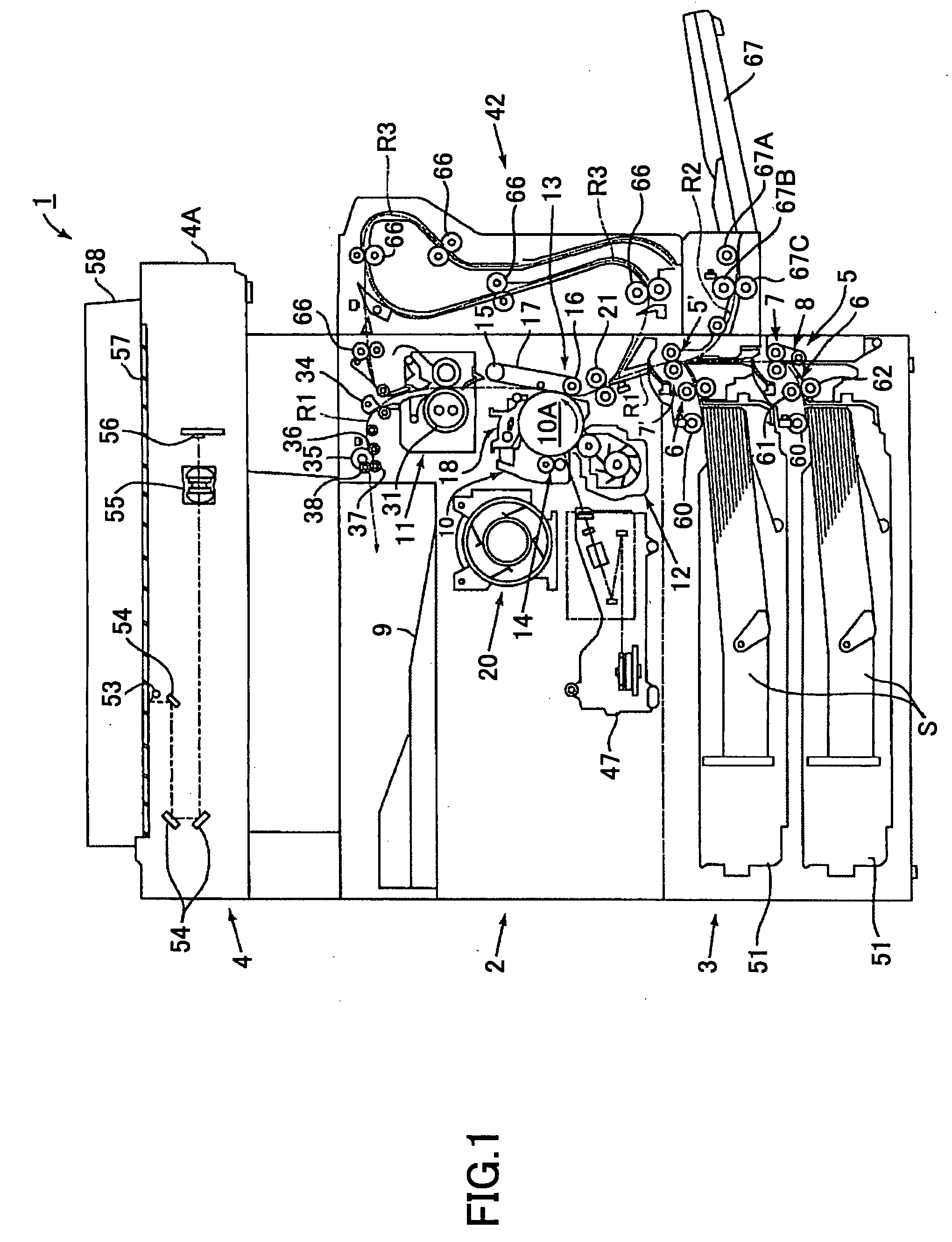
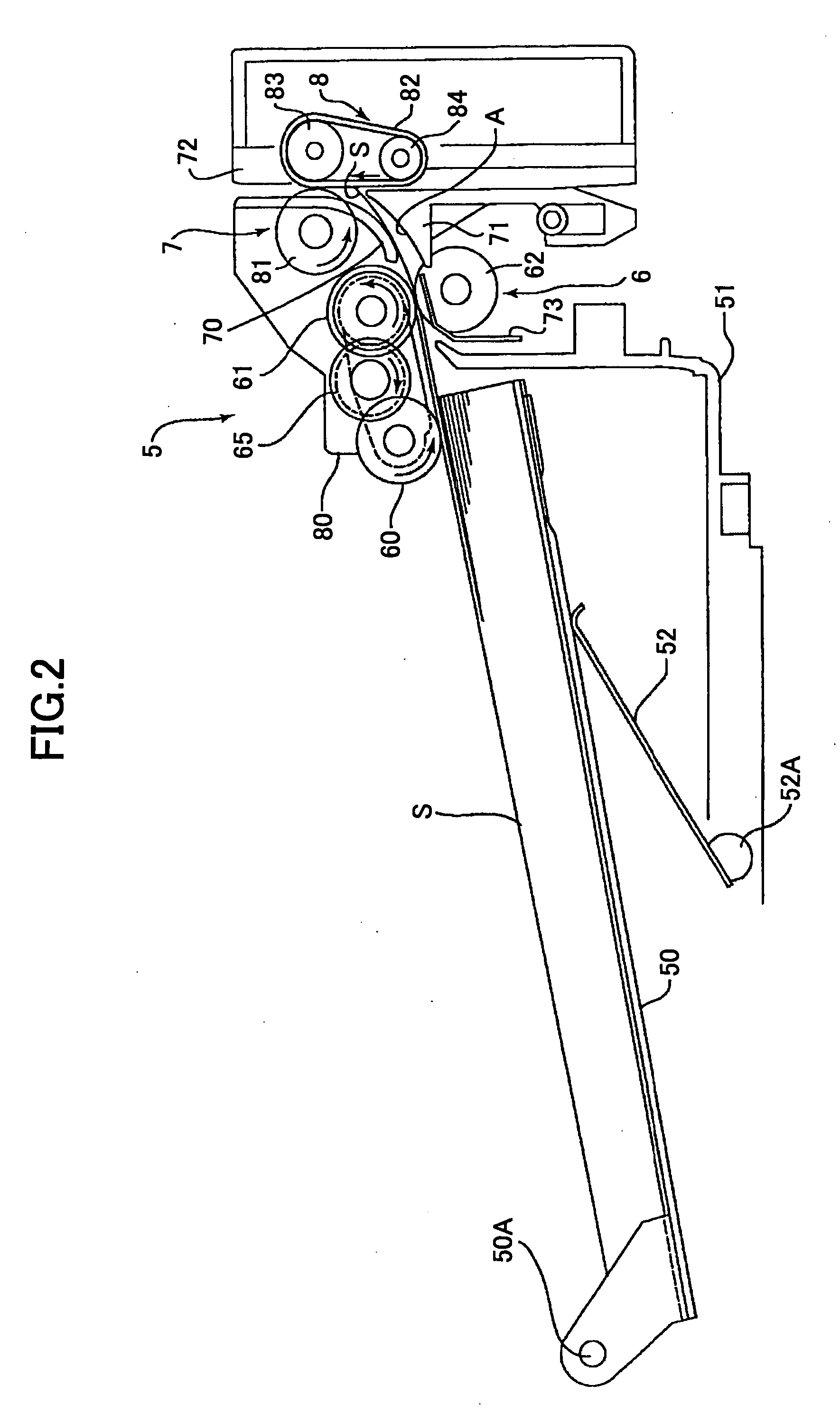
[0077]FIGS. 1-3 illustrate a first embodiment of a sheet conveying apparatus to which the present invention is applied and an image forming apparatus including the same. FIG. 1 illustrates an overall configuration of a copier 1 as an example of an image forming apparatus according to an embodiment to which the present invention is applied.

[0078]The copier 1 is a monochrome copier that scans an image from a face of an original and forms a copied image onto various sheet-type recording media (hereinafter, “sheet”) such as recording paper, transfer paper, paper sheets, and OHP transparencies. The copier 1 includes an image forming apparatus main unit 2, a sheet feeding device 3 on which the image forming apparatus main unit 2 is mounted, and an original scanning device 4 attached on the image forming apparatus main unit 2. The image forming apparatus main unit 2 includes an image forming section for performing a predetermined image forming process based on a scanned original image. The...

first practical example

[0149]Next, a reference first practical example (hereinafter, “first practical example”) of the first embodiment to which the present invention is applied is described. A comparative test was conducted to compare the sheet conveying (sheet passing) properties of a copier according to the first embodiment to which the present invention is applied (indicated as “belt method” in Table 1) and a copier according to a conventional method (indicated as “conventional method” in Table 1). Among the components of “imagio Neo 453” manufactured by RICOH, only the sheet feeding device was modified to be used for the “belt method” of this test. The modified sheet feeding device used for the “belt method” basically has the same configurations and specifications as that of the sheet feeding device 3 of the sheet conveying apparatus 5 shown in FIGS. 1-3. For the “conventional method”, “imagio Neo 453” manufactured by RICOH was used, in this case including a sheet feeding device with a conventional s...

modification examples of first embodiment

[0174]FIGS. 6A-6C illustrate modification examples of the first embodiment to which the present invention is applied.

[0175]As shown in FIG. 6A, one member of the pair of rollers facing / contacting each other in the first conveying unit 6 can be the belt conveying unit 8. Furthermore, as shown in FIG. 6B, one member of the pair of rollers facing / contacting each other in the in the first conveying unit 6 and one member of the pair of rollers facing / contacting each other in the second conveying unit 7 can be the belt conveying unit 8 and a belt conveying unit 8′, respectively. Furthermore, as shown in FIG. 6C, a separate, independent belt conveying unit 8 can be provided as a moving / guiding unit alternative to one member of the pair of rollers in the first conveying unit 6 arranged on the upstream side or one member of the pair of rollers in the second conveying unit 7 arranged on the downstream side, and arranged between the first conveying unit 6 and the second conveying unit 7.

[0176]...


PUM


Abstract

A disclosed sheet conveying apparatus includes a first conveying unit configured to convey a sheet in a first sheet conveying direction; and a second conveying unit arranged on a downstream side of the first conveying unit in the first sheet conveying direction and configured to convey the sheet conveyed by the first conveying unit in a second sheet conveying direction different from the first sheet conveying direction. At least the second conveying unit acts as a holding/conveying unit with a holding section to hold and convey the sheet and includes a moving/guiding unit arranged along an outer side of a sheet conveying path extending between the first conveying unit and the second conveying unit. The moving/guiding unit moves/guides the sheet toward the holding section of the second conveying unit, and is arranged in a discontinuous manner along a sheet width direction orthogonal to the first sheet conveying direction so as to contact at least one part of the sheet in the sheet width direction.

Description

BACKGROUND OF THE INVENTION[0001]1. Field of the Invention[0002]The present invention relates to a sheet conveying apparatus; an image scanning apparatus such as a copier, a facsimile machine, a printer, a printing machine, an inkjet recording device, and a scanner provided with the sheet conveying apparatus; or an image forming apparatus such as a multifunction peripheral combining functions of at least two of the above.[0003]2. Description of the Related Art[0004]Conventionally, in order to reduce the overall sizes of image forming apparatuses including copiers such as a PPC (plain paper copier) and an electrophotographic copier, facsimile machines, printers such as a laser beam printer, printing machines, and inkjet recording devices, the sizes of conveying units provided therein also tend to be reduced. Specifically, the conveying unit is used for conveying a medium or a sheet-type recording medium onto which an image is formed (hereinafter, “sheet”). The sheet is conveyed from ...

Claims


Application Information

Patent Timeline
Patent Type & Authority Applications(United States)
IPC IPC(8): B65H5/08
CPCB65H3/06B65H5/025B65H5/36B65H2404/6111G03G15/6529G03G15/6594G03G2215/00405G03G2215/00481G03G15/1665G03G15/235G03G15/6558G03G15/00
Inventor SAGAWA, YASUHIROUEDA, KENJIUEDA, MASAYUKIWATASE, HIROYUKIOKAMOTO, NAOYUKIISHIKAWA, YOSHIKUNIKAJIYAMA, HIROSHIAKIMOTO, TAMIYA
Owner RICOH KK
Why Eureka
Try Eureka