
System and method for video processing and display

a video processing and display technology, applied in the field of video processing and display, can solve the problems of not providing any real sense of enhanced “immersion” in the scene, achieving a wide-angle display, high-definition camera and display system,

Inactive Publication Date: 2007-10-25
BRITISH BROADCASTING CORP
View PDF5 Cites 13 Cited by
  • Summary
  • Abstract
  • Description
  • Claims
  • Application Information

AI Technical Summary

Benefits of technology

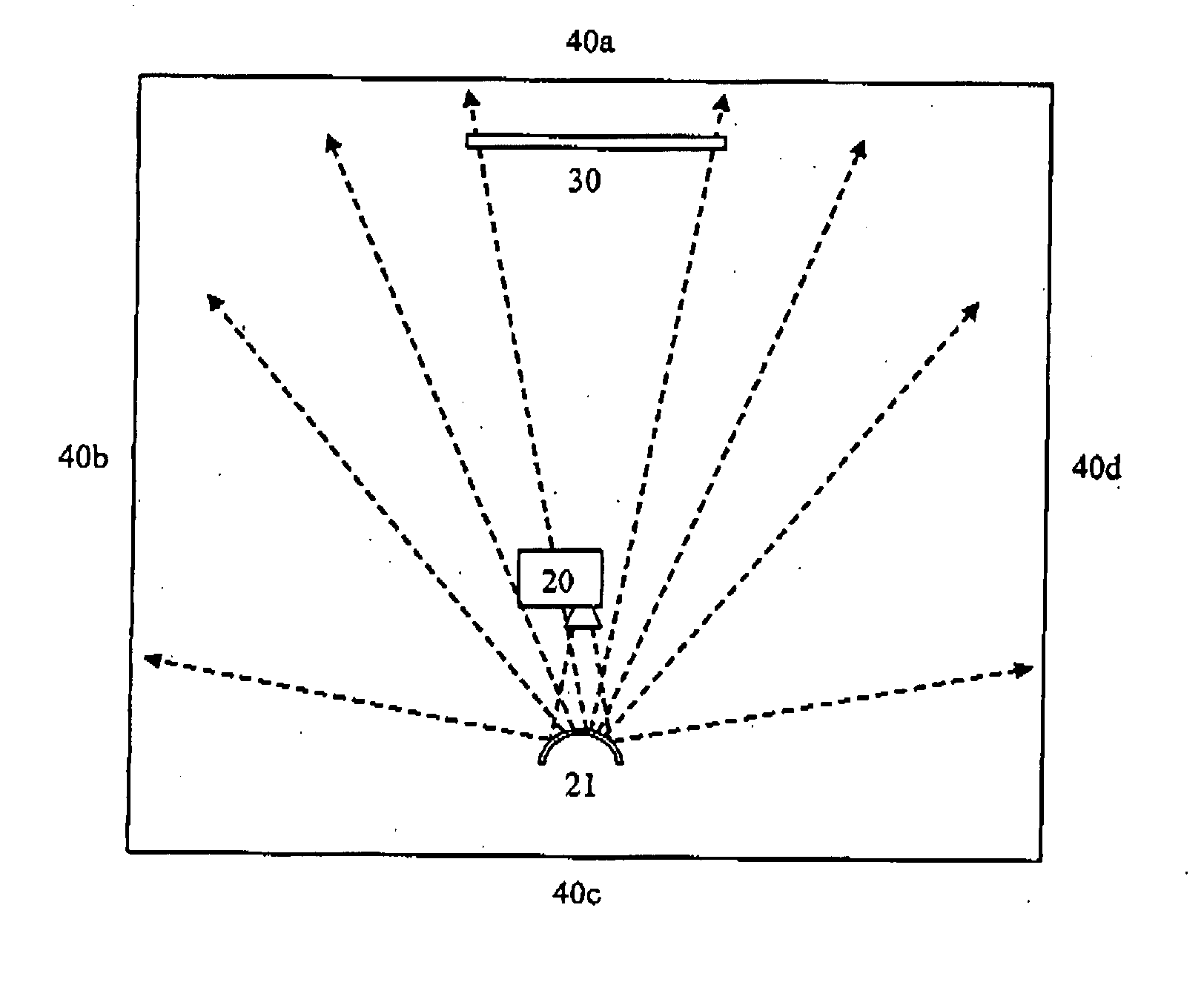
[0025] Embodiments may fill a large portion of the eye's view—both the central and peripheral vision areas—and thereby increase the sense of immersion in the presented scene.
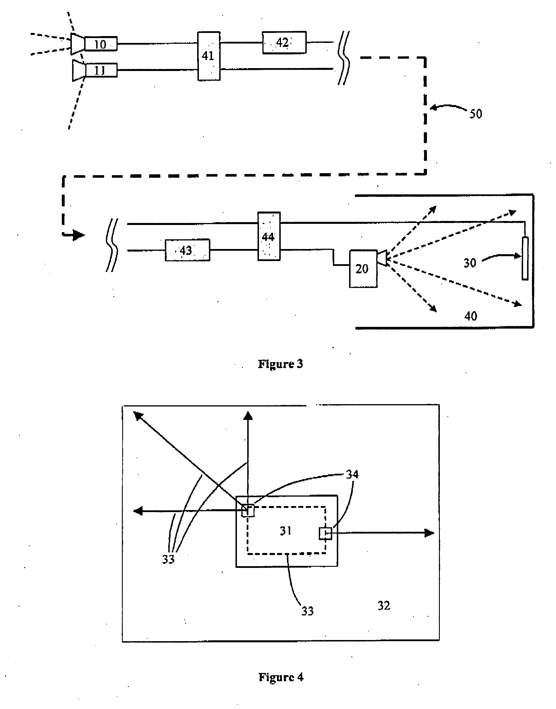
[0027] Both main and secondary recordings may be made available as two separate but synchronous video streams. Those viewers with the required playback equipment can use the second ‘surround’ video stream to project an image onto the walls, floor and ceiling of their viewing environment and substantially fill their field of view. Real-time image manipulation software is preferably provided to remove the distortion imposed on the image by the geometry (or other characteristics) of the room. The portion of the projected image that would fall on the normal TV display is typically blanked, but may be at a lower intensity so as not to be problematic.

Problems solved by technology

Thus this may improve perception but does not provide any real sense of enhanced “immersion” in the scene, as it occupies only a small proportion of the viewer's visual field, and is only very weakly related to the picture content.
Conventional methods for achieving a wide-angle display, such as IMAX, require a very high-definition camera and display system, and are unsuitable for use in a domestic environment.
The data rate required to deliver such a high-definition image over a broadcast link makes deploying such a system impractical.
Furthermore, were such a system to be set up in a domestic environment, any conventional TV set would have to be removed to make space, interfering with viewing of conventional TV.

Method used


Image

  • System and method for video processing and display
  • System and method for video processing and display
  • System and method for video processing and display

Examples


Embodiment Construction

[0039] The following description is presented to enable one of ordinary skill in the art to make and use the invention as provided in the context of a particular application and its requirements. Various modifications to the described embodiments will be apparent to those with skill in the art, and the general principles defined herein may be applied to other embodiments. Therefore, the present invention is not intended to be limited to the particular embodiments shown and described, but is to be accorded the widest scope consistent with the principles and novel features disclosed. In some cases, well-known methods, procedures, and components have not been described in detail so as not to obscure the present invention.

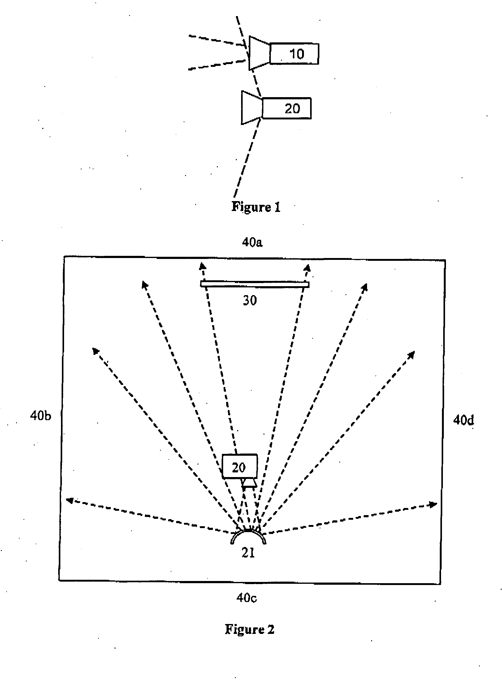
[0040] Referring to FIG. 1, two cameras 10 and 11 are used which are rigidly mounted together in a frame. The cameras can be handheld, mounted on a tripod or supported in any other appropriate manner. The main camera 10 is free to be moved to frame shots as usual; the...


PUM


Abstract

To supplement a video display on a conventional television, a surround video stream may be projected onto wall and other surfaces adjacent the television. The surround video stream may derive from a wide angle lens camera positioned alongside the main camera. The surround video stream may be processed in a local processor to compensate for departures from planar geometry in the wall surfaces. Where no surround video stream is received, a video processor may synthesize a surround video stream from the main video signal. Moving objects represented in the main video signal may be synthesized in the surround video to provide the perception of movement across the viewer's full field of view.

Description

PRIOR APPLICATION DATA [0001] The present application claims priority from prior UK application 0606965.2 filed Apr. 6, 2006, incorporated by reference herein in its entirety. FIELD OF THE INVENTION[0002] The present invention relates to video processing and display. For example, some embodiments aim to provide a viewer with a wider field-of-view—leading to a greater sense of immersion than a traditional video presentation—without requiring a larger television or display screen. BACKGROUND OF THE INVENTION [0003] Traditional television viewing in domestic environments usually includes a single, television monitor. In some situations, a flat-screen display or projector may be used to provide a larger viewing area. It is reasonably common for viewers to choose to augment or replace the audio capabilities of the display with an external stereo or surround sound hi-fi system. [0004] One known system (Philips Ambilight FlatTV TM) includes a built in soft light, which emanates onto the wa...

Claims


Application Information

Patent Timeline
Patent Type & Authority Applications(United States)
IPC IPC(8): H04N7/00H04N21/2187H04N21/431
CPCG03B21/00H04N5/74G09G2310/0232G09G3/002G03B21/006H04N5/262H04N23/00
Inventor THOMAS, GRAHAM ALEXANDERSARGEANT, TIMOTHY JOHNCHANDARIA, JIGNAWEIR, BRUCE ALEXANDERDEBENHAM, PAUL RICHARD
Owner BRITISH BROADCASTING CORP
Learn More