Large dynamic range Shack-Hartmann wavefront sensor

a wavefront sensor, large-dynamic technology, applied in the direction of measurement devices, instruments, optical radiation measurement, etc., can solve the problems of indeterminate focus of the second lenslet, proportionate decrease of the sensitivity of the wavefront sensor, and (1) or (2), so as to increase the dynamic range of increase the shack-hartmann wavefront sensor

Active Publication Date: 2007-10-25
UNIVERSITY OF ROCHESTER
View PDF4 Cites 18 Cited by
  • Summary
  • Abstract
  • Description
  • Claims
  • Application Information

AI Technical Summary

Benefits of technology

[0013] One way of increasing the dynamic range of a Shack-Hartmann wavefront sensor is by blocking and unblocking individual lenslets within the array thereof in a temporally predetermined manner. While a particular lenslet is blocked, the detector subaperture associated with that lenslet is precluded from receiving light incident on that lenslet. Thus, the detector subaperture for the blocked lenslet is available to receive a signal from another, unblocked lenslet in a potentially unambiguous manner. The blocked lenslet may then be unblocked while simultaneously blocking other lenslets in a prescribed manner. Thus, a predetermined sequence of blocking lenslets within the lenslet array may be used to increase the dynamic range of a Shack-Hartmann wavefront sensor

Problems solved by technology

If the slope of a wavefront at one or more of the lenslets exceeds such a predetermined limit, the focus spots from such lenslets move into the subaperture of another lenslet, resulting in one of the following problems: (1) multiple spots are created within a single subaperture, (2) multiple spots overlap within a single subaperture, and (3) spots switching between subapertures.
The presence of the focus from the first lenslet in the second detector subaperture results in an ambiguity, since it cannot be determined, a priori, from which lenslet the focused light came.
If the wavefront slope at the second lenslet does not exceed the maximum limit, problems (1) or (2) can result.
In the case of problem (2), the focus of the second lenslet is indeterminate, since there is insufficient information to determine whether the second focus spot is located at that of another lenslet or the second focus spot is absent.
If the wavefront slope at the second lenslet does exceed the maximum limit, problem (3) results.
In this case an error can results since the focus spots will usually not be associated with the correct lenslet.
These problems can exist between two lenslets or several lenslets.
The drawback to this choice is that the sensitivity of the wavefront sensor is decreased proportionately if all other system parameters remain the same as they were in the longer focal length lenslet design.

Method used


Image

  • Large dynamic range Shack-Hartmann wavefront sensor
  • Large dynamic range Shack-Hartmann wavefront sensor
  • Large dynamic range Shack-Hartmann wavefront sensor

Examples


Embodiment Construction

[0036] These and other embodiments of the present disclosure will also become readily apparent to those skilled in the art from the following detailed description of preferred embodiments having reference to the attached figures; however, the disclosure is not limited to any particular embodiment(s) disclosed herein. Accordingly, the scope of the present disclosure is intended to be defined only by reference to the appended claims.

Wavefront Sensor

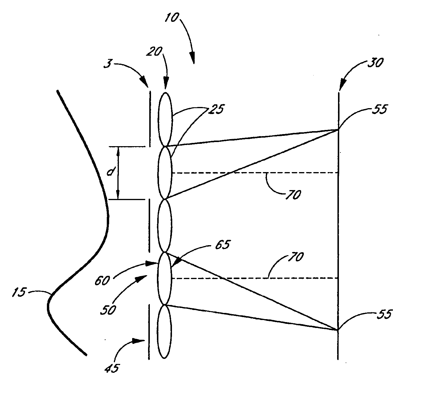
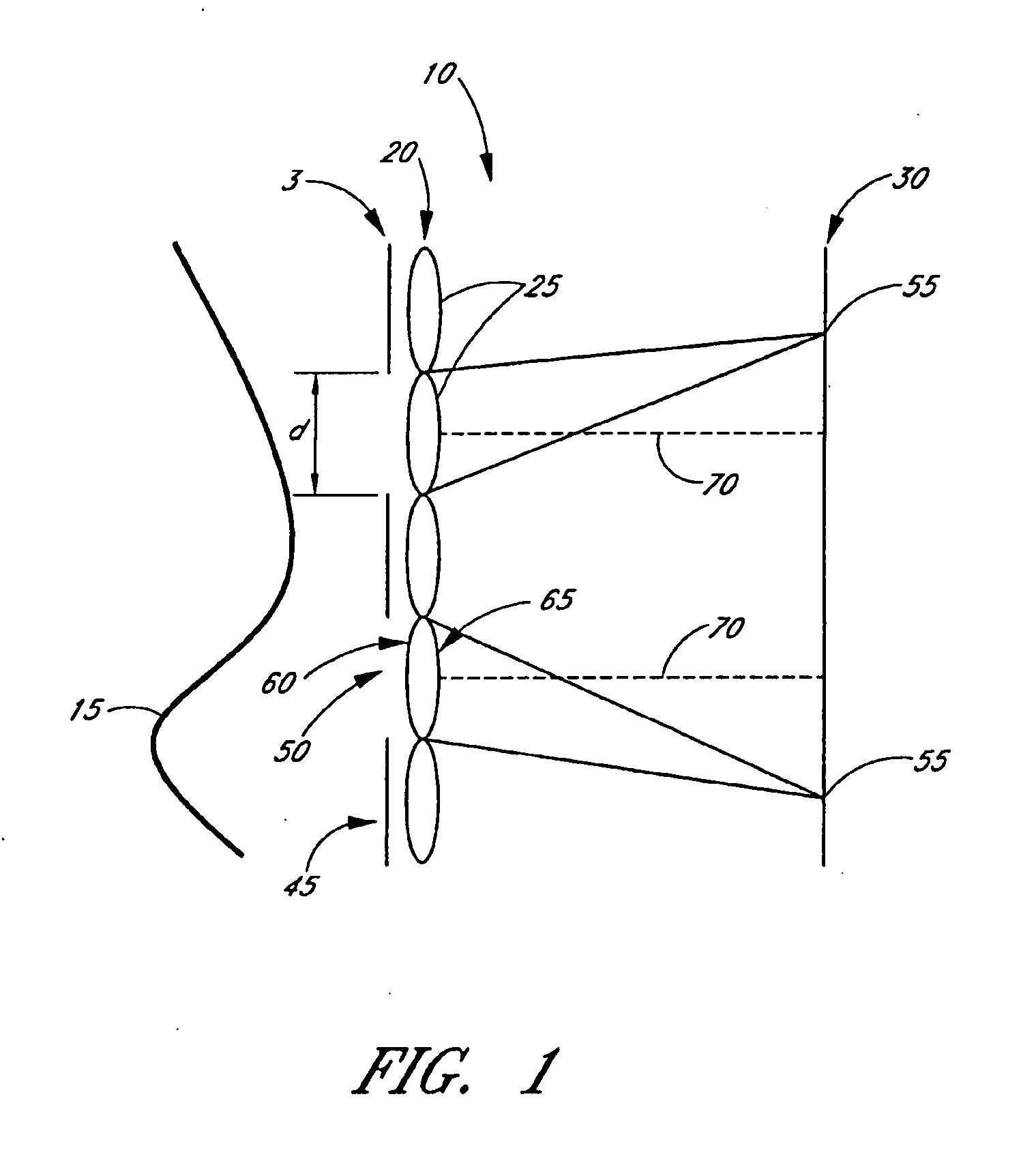
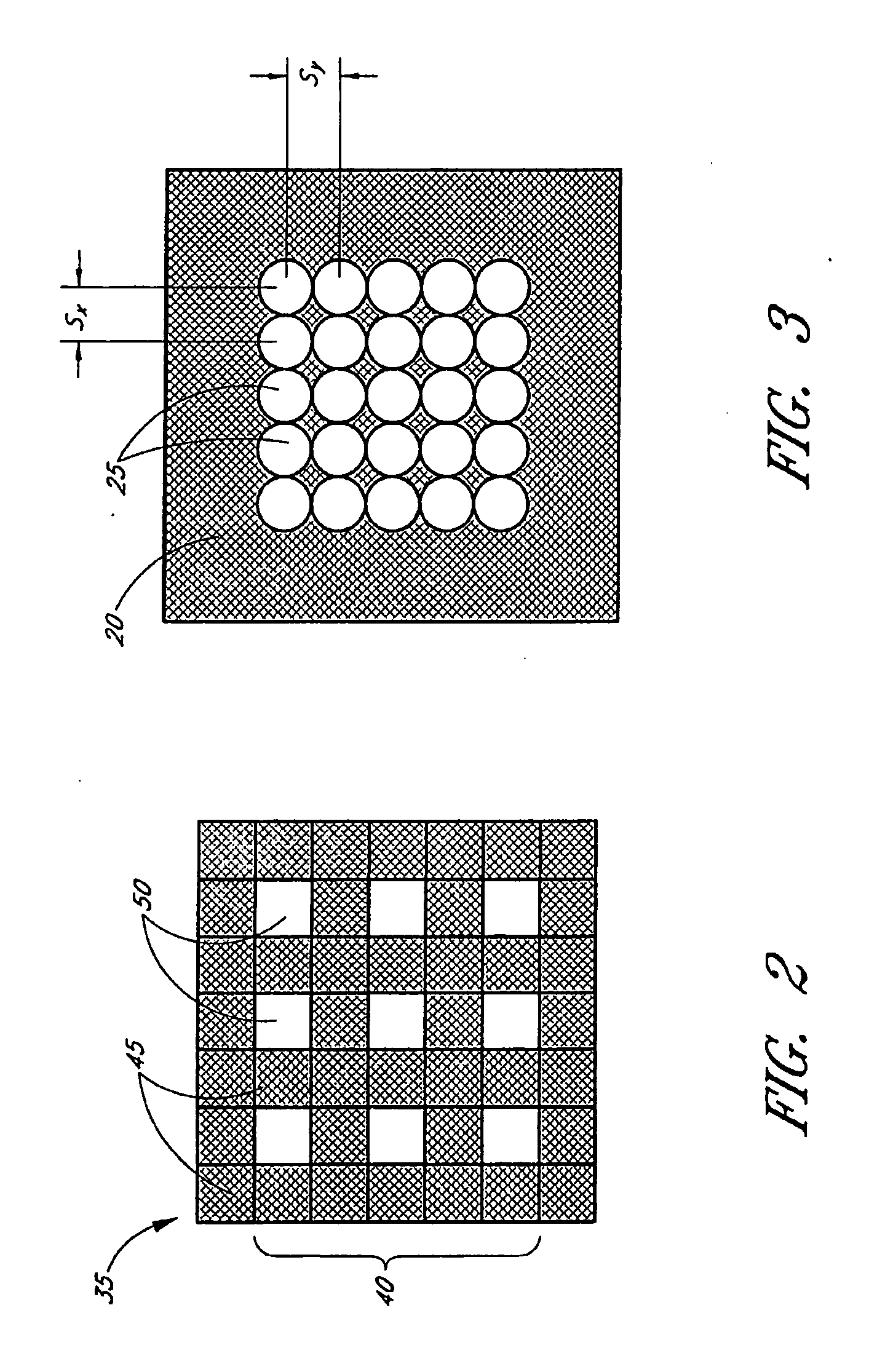
[0037]FIGS. 1, 2, and 3 schematically illustrate a wavefront sensor 10 for measuring a wavefront 15. The wavefront sensor 10 comprises an array 20 of lenslets 25, a detector array 30, and a mask 35 having a temporally fixed pattern 40 containing one or more opaque regions 45 that are substantially opaque to light from the wavefront 15 and one or more transmissive regions 50 that are transmissive of light from the wavefront 15. The mask 35 and the array 20 of lenslets 25 are disposed such that light from the wavefront 15 that is transmitt...


PUM

PropertyMeasurementUnit
diameteraaaaaaaaaa
diameteraaaaaaaaaa
diametersaaaaaaaaaa

Abstract

A wavefront sensor for measuring a wavefront contains an array of lenslets, a detector array, and a mask having a temporally fixed pattern containing one or more opaque regions that are substantially opaque to light from the wavefront. The mask comprises one or more transmissive regions that are transmissive of light from the wavefront. The mask and the array of lenslets are disposed such that light from the wavefront that is transmitted by the transmissive regions is focused by onto the detector array by the array of lenslets. The mask is adapted to be selectably disposed to any one of a plurality of predetermined positions, wherein a different group of lenslets from the array focuses light from the wavefront onto the detector array depending on which of the plurality of predetermined positions is selected.

Description

RELATED APPLICATIONS [0001] This application is a continuation-in-part of U.S. application Ser. No. 10 / 778,888, filed Feb. 13, 2004, which claims the priority benefit of U.S. Provisional Application No. 60 / 447,344, filed Feb. 13, 2003, both of which are hereby incorporated in their entirety by reference.GOVERNMENT LICENSE RIGHTS [0002] The U.S. Government has a paid-up license in this invention and the right in limited circumstances to require the patent owner to license others on reasonable terms as provided for by the terms of Contract / Grant Nos. 5R01EY14999, awarded by the National Institutes of Health.BACKGROUND OF THE INVENTIONS [0003] 1. Field of the Inventions [0004] The present disclosure is directed to a wavefront measuring device, and more specifically, to a Shack-Hartmann type wavefront sensor with a large dynamic range. [0005] 2. Description of the Related Art [0006] The Shack-Hartmann technique is commonly used for determining wavefront shape or error from an ideal plan...

Claims


Application Information

Patent Timeline
Patent Type & Authority Applications(United States)
IPC IPC(8): G02F1/01G01J1/00G01J9/00
CPCG01J9/00
Inventor YOON, GEUNYOUNG
Owner UNIVERSITY OF ROCHESTER
Why Eureka
Try Eureka