Lighting unit reflector

Inactive Publication Date: 2007-10-25
LEOTEK ELECTRONICS
View PDF15 Cites 48 Cited by
  • Summary
  • Abstract
  • Description
  • Claims
  • Application Information

AI Technical Summary

Benefits of technology

[0011] The present invention solves the aforementioned problems by providing multiple and varying curved-surface re

Problems solved by technology

Such designs, however, often yield narrow light patterns that are focused on a limited area just below the lighting unit, if the shape of the reflector is not appropriately designed, which is not desirable

Method used


Image

  • Lighting unit reflector
  • Lighting unit reflector
  • Lighting unit reflector

Examples


Example

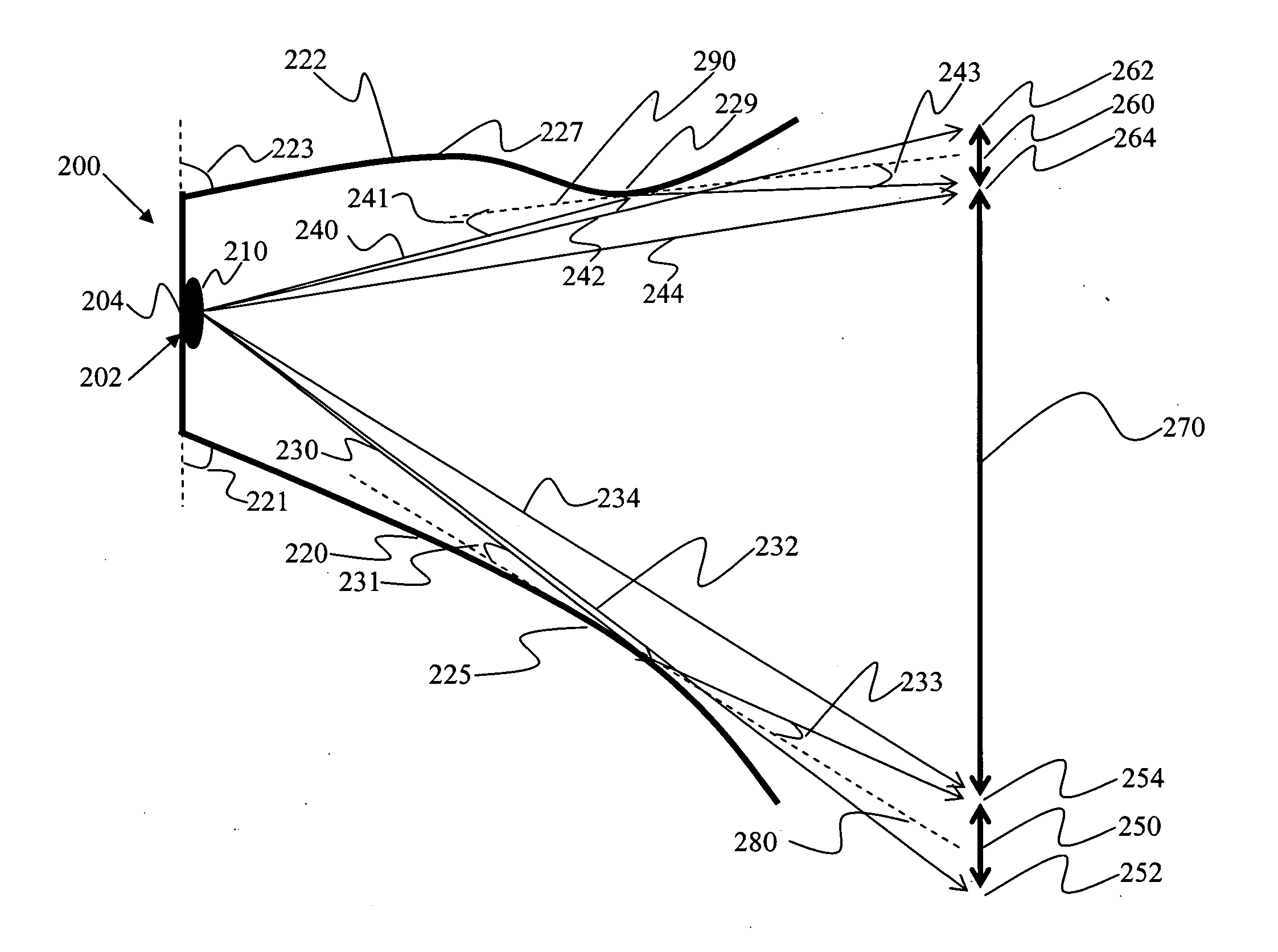
[0022] The present invention is an improved reflector design for LED lighting unit applications. More particularly, the present invention is a method and apparatus for efficiently redirecting light from LED lighting unit applications so as to reduce dark bands and increase the scope of a lighting unit's 50% peak intensity contour line.

[0023] The present invention provides a curved-surface reflector design, which substantially reduces dark band areas and distributes light to a wider area than conventional designs. FIG. 3 illustrates a cross-sectional view of a lighting unit 200 having a curved-surface multi-LED reflector tray design. As illustrated, lighting unit 200 comprises a light source 210 mounted onto a reflector assembly 202. Reflector assembly 202 includes a back plate 204, and lower and upper curved reflectors 220, 222 extending therefrom (although back plate 204 can be omitted or formed integrally as part of the curved reflectors 220, 222). In a preferred embodiment, lowe...


PUM


Abstract

A lighting unit that includes a light source and a reflector assembly upon which the light source is mounted. The reflector assembly includes a first reflector having a first curved reflective surface extending away from the light source, and a second reflector having a second curved reflective surface extending away from the light source. The first curved reflective surface faces and opposes the second curved reflective surface. The first curved reflective surface has a curvature that is different from that of the second curved reflective surface. The first and second curved reflective surfaces both preferably terminate in convexities that reduce the size of dark band areas of illumination.

Description

[0001] This application claims the benefit of U.S. Provisional Application No. 60 / 789,726, filed Apr. 5, 2005, and entitled Improved LED Luminaire Reflector Design.FIELD OF THE INVENTION [0002] The present invention relates to a reflector design especially ideal for Light-Emitting Diode (LED) lighting unit (luminaire) applications. More particularly, the present invention relates to a method and apparatus for efficiently redirecting light from LED applications so as to provide desirable angular distributions. BACKGROUND OF THE INVENTION [0003] Light-Emitting Diodes (LEDs) have been used in many applications to replace conventional incandescent lamps, fluorescent lamps, neon tube and fiber optics light sources in order to reduce costs and to increase reliability. Due to the fact that LEDs consume less electrical energy than most conventional light sources, while exhibiting a much longer lifetime, many designs have been invented for various applications, such as traffic signal lights,...

Claims


Application Information

Patent Timeline
IPC IPC(8): F21V7/00
CPCF21V7/005F21Y2101/02F21W2131/103F21V7/09F21Y2115/10
Inventor WANG, SHIH CHANGLAU, BOK LIANWU, FENGTU, CHIN-WANGWU, CHEN-HO
Owner LEOTEK ELECTRONICS
Why Eureka
Try Eureka