Coupling for tubular elements

a tubular element and coupling technology, applied in the direction of couplings, tube connectors, coupling devices, etc., can solve the problems of unplanned air accumulation in such couplings, and the flow of fluid through the coupling often has to be interrupted

Inactive Publication Date: 2007-10-25
NOVALUNG
View PDF22 Cites 13 Cited by
  • Summary
  • Abstract
  • Description
  • Claims
  • Application Information

AI Technical Summary

Benefits of technology

[0032] The effect of this measure is that, even in the locking position in which the channel is isolated from the environment,

Problems solved by technology

However, it has been found that undesired accumulation of air may take place in such couplings.
Thi

Method used


Image

  • Coupling for tubular elements
  • Coupling for tubular elements
  • Coupling for tubular elements

Examples


Embodiment Construction

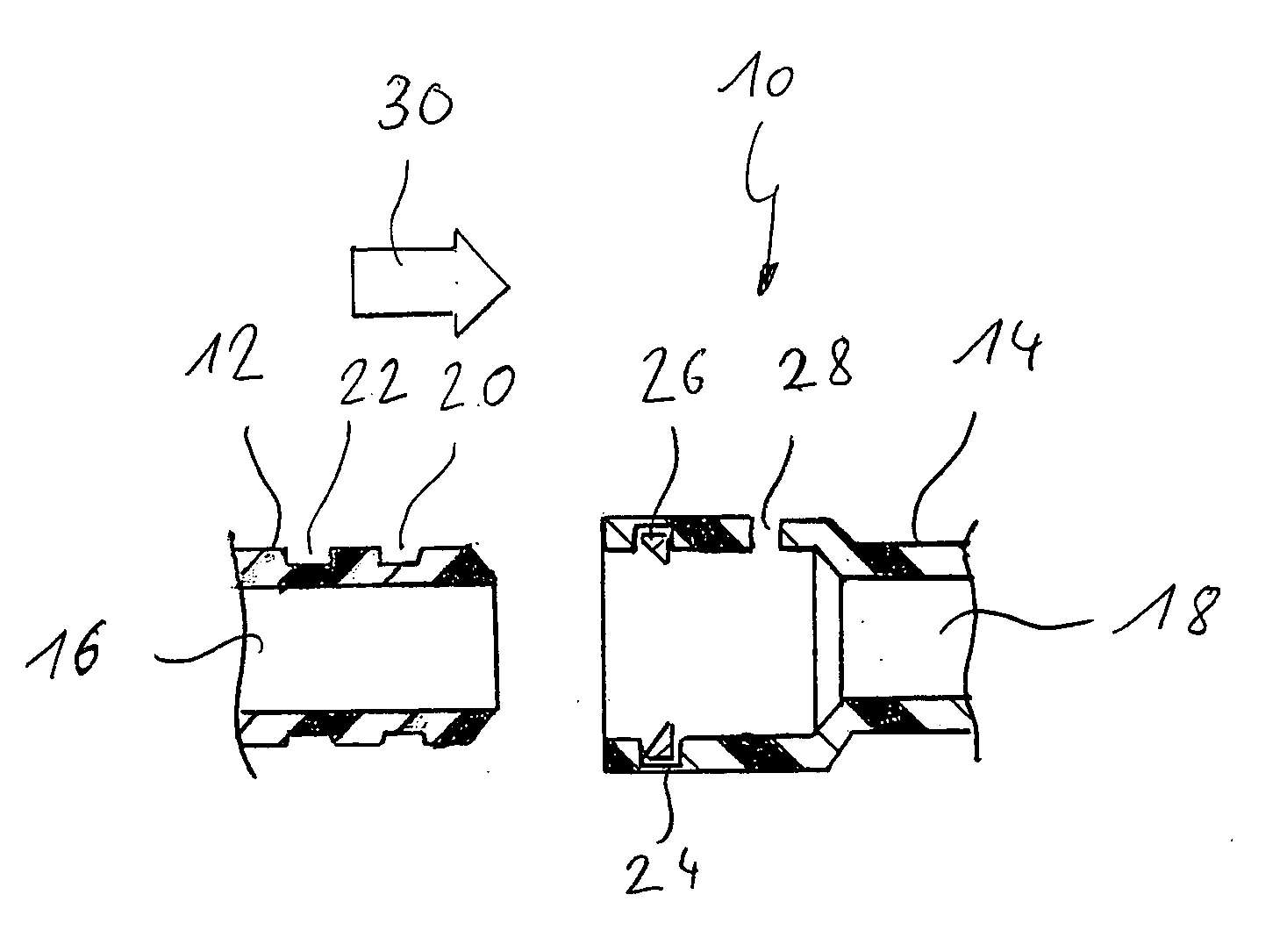
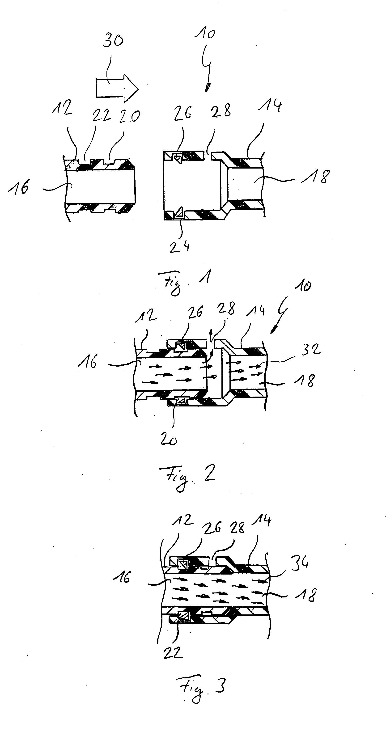
[0039] In FIG. 1, a coupling is designated in its entirety by reference number 10.

[0040] The coupling 10 comprises a plug 12 and a socket 14. Along its longitudinal axis, the plug 12 has a channel 16 for a fluid, and the socket 14, along its longitudinal axis, has a corresponding channel 18. Both the plug 12 and the socket 14 are in this case made of plastic.

[0041] A first annular groove 20 and a second annular groove 22 are formed in an outer circumferential surface of the plug 12.

[0042] An annular groove 24 is formed in an inner circumferential surface of the socket 14. A slotted ring 26 with a triangular cross section is arranged in this annular groove 24. The ring 26 is arranged in the annular groove 24 in such a way that at least part of it protrudes above the inner circumferential surface of the socket 14.

[0043] The socket 14 also has an opening 28, which is here designed as a simple bore through which the channel 18 is connected to the environment.

[0044] The plug 12 is n...


PUM

PropertyMeasurementUnit
Areaaaaaaaaaaa

Abstract

The invention relates to a coupling for tubular elements, with at least one plug and one socket, which plug can be inserted into the socket and can be locked therein, and both the plug and the socket have, extending approximately along their longitudinal axis, a channel for a fluid, said channel being arranged in such a way that the fluid can flow through the coupling in a locked state thereof. The plug can be locked in the socket in at least two locking positions, and the socket and/or the plug has at least one opening such that, in a first locking position, the opening connects the channel for a fluid to the environment, and, in a second locking position, the channel for a fluid is isolated from the environment. The invention relates further to a cannula that comprises such a coupling.

Description

CROSS-REFERENCE TO RELATED APPLICATIONS [0001] This application claims priority under 35 U.S.C. § 119(d) from German patent application No. 10 2006 016 211.0 filed Apr. 3, 2006. The content of the above patent application is incorporated by reference herein in its entirety. [0002] 1. Field of the Invention [0003] The present invention relates to a coupling for tubular elements, with at least one plug and one socket, which plug can be inserted into the socket and can be locked therein, and both the plug and the socket have, extending approximately along their longitudinal axis, a channel for a fluid, said channel being arranged in such a way that the fluid can flow through the coupling in a locked state thereof. [0004] The invention further relates to a cannula that comprises such a coupling. [0005] For coupling tubular elements, it was for a long time customary to use short tube sections whose external diameter was slightly greater than the internal diameter of the tubular elements ...

Claims


Application Information

Patent Timeline
IPC IPC(8): H01R13/62
CPCA61B2017/00477A61M39/1011A61M39/225F16L47/32F16L37/00F16L41/02A61M2039/1027
Inventor SPRANGER, MARTINJOOST, THILO
Owner NOVALUNG
Why Eureka
Try Eureka