Computer workload redistribution

a workload and computer technology, applied in the field of computer workload, can solve the problems of low utilization rate of computers, waste of 75% of power, and full power

Active Publication Date: 2007-10-25
HEWLETT-PACKARD ENTERPRISE DEV LP
View PDF23 Cites 159 Cited by
  • Summary
  • Abstract
  • Description
  • Claims
  • Application Information

AI Technical Summary

Problems solved by technology

One of the classic challenges for information technology (IT) managers is to insure that they have capacity for their peak computational loads.
As a result, they may typically have low utilization of their computers (for example 25% of capacity) except for the rare occurrence of 100% peak.
The ISP has their servers on all the time consuming power even though utilization during most of the day may be less than 25% of the capacity; as a result, at least 75% of the power is wasted.
To deal with this, IT managers have done the following: 1) they buy enough computers to deal with peak demands; the disadvantage of this is that full power is being used by computers even though they are just partially utilized; 2) they use “Instant Capacity” (ICAP, available from Hewlett-Packard Company) and comparable solutions that allow them to add processors based on demand; the disadvantage is that while the data center owner is not paying for the unused hardware, it is still paying for the power consumed by it; and 3) they buy computers to deal with the average loads; the disadvantage of this is that the IT manager's company then cannot support peak demand and thus loses revenue.
However, such methods are not optimal.

Method used


Image

  • Computer workload redistribution
  • Computer workload redistribution
  • Computer workload redistribution

Examples


Embodiment Construction

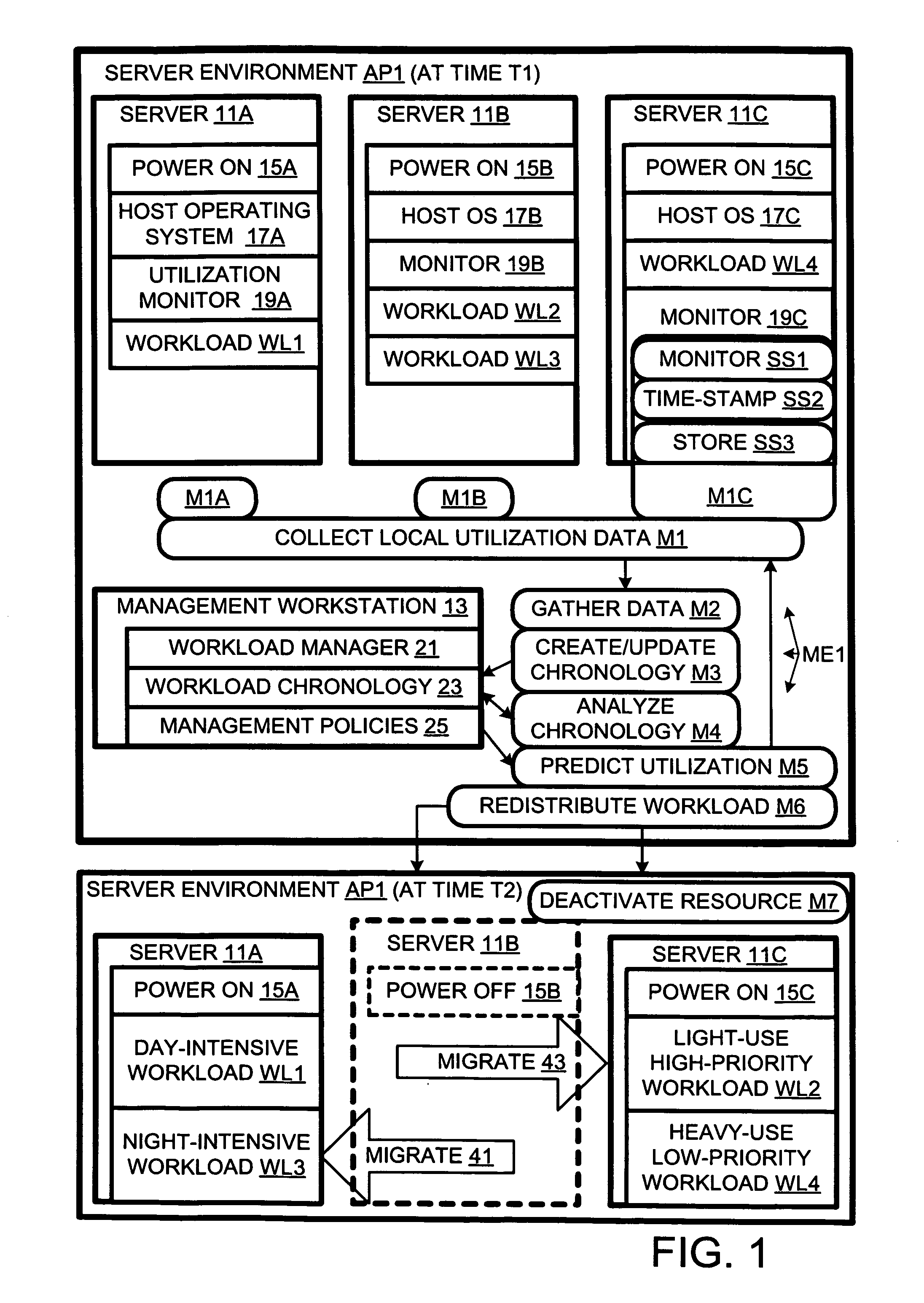
[0009] In the course of the present invention, it was realized that the foregoing methods based on current measurements of utilization, while beneficial, were limited in what they could accomplish. They are limited because they control parameters that can be changed relatively quickly in response to changes in power demands. It was further realized that, if future use could be predicted, applications could be assigned to servers in a way that would minimize the number of servers without impacting performance. This would reduce energy consumption and maintenance costs. Furthermore, there would be less need to overbuy to avoid performance bottlenecks.

[0010] A server environment AP1 in accordance with the present invention is shown in FIG. 1 at times T1 and T2. Server environment AP1 includes three servers 11A, 11B, and 11C, and a management workstation 13. Servers 11A, 11B, and 11C have reduced power modes. In the illustrated embodiment, servers 11A, 11B, and 11C, and management work...


PUM


Abstract

The present invention provides for redistributing workloads among computers to optimize resource utilization. Utilization by software workloads of computer resources is monitored to yield utilization data. A utilization chronology is updated using the utilization data. The chronology is analyzed to yield resource utilization predictions. The workloads are redistributed among the resources at least in part as function of said predictions.

Description

BACKGROUND OF THE INVENTION [0001] Herein, related art is discussed to aid in understanding the invention. Related art labeled “prior art” is admitted prior art; related art not labeled “prior art” is not admitted prior art. [0002] One of the classic challenges for information technology (IT) managers is to insure that they have capacity for their peak computational loads. As a result, they may typically have low utilization of their computers (for example 25% of capacity) except for the rare occurrence of 100% peak. For example, an Internet service provider (ISP), such as AOL, may have peak usage of their web servers once a day during the late evening hours since most of their clients surf the web after dinner. The ISP has their servers on all the time consuming power even though utilization during most of the day may be less than 25% of the capacity; as a result, at least 75% of the power is wasted. In addition, servers are usually not turned off or put in sleep mode (as is done w...

Claims


Application Information

Patent Timeline
Patent Type & Authority Applications(United States)
IPC IPC(8): G06F9/46
CPCG06F11/3409G06F11/3466G06F11/3452G06F11/3433
Inventor BELADY, CHRISTIAN L.VADEN, THOMAS L.HERINGTON, DANIEL EDWARDTURICCHI, THOMAS EDWIN JR.
Owner HEWLETT-PACKARD ENTERPRISE DEV LP
Why Eureka
Try Eureka