Automatic patient transfer system

US20070251004A1Inactive Publication Date: 2007-11-01WANG XIAO DONG

Image

  • Automatic patient transfer system
  • Automatic patient transfer system
  • Automatic patient transfer system

Examples


Embodiment Construction

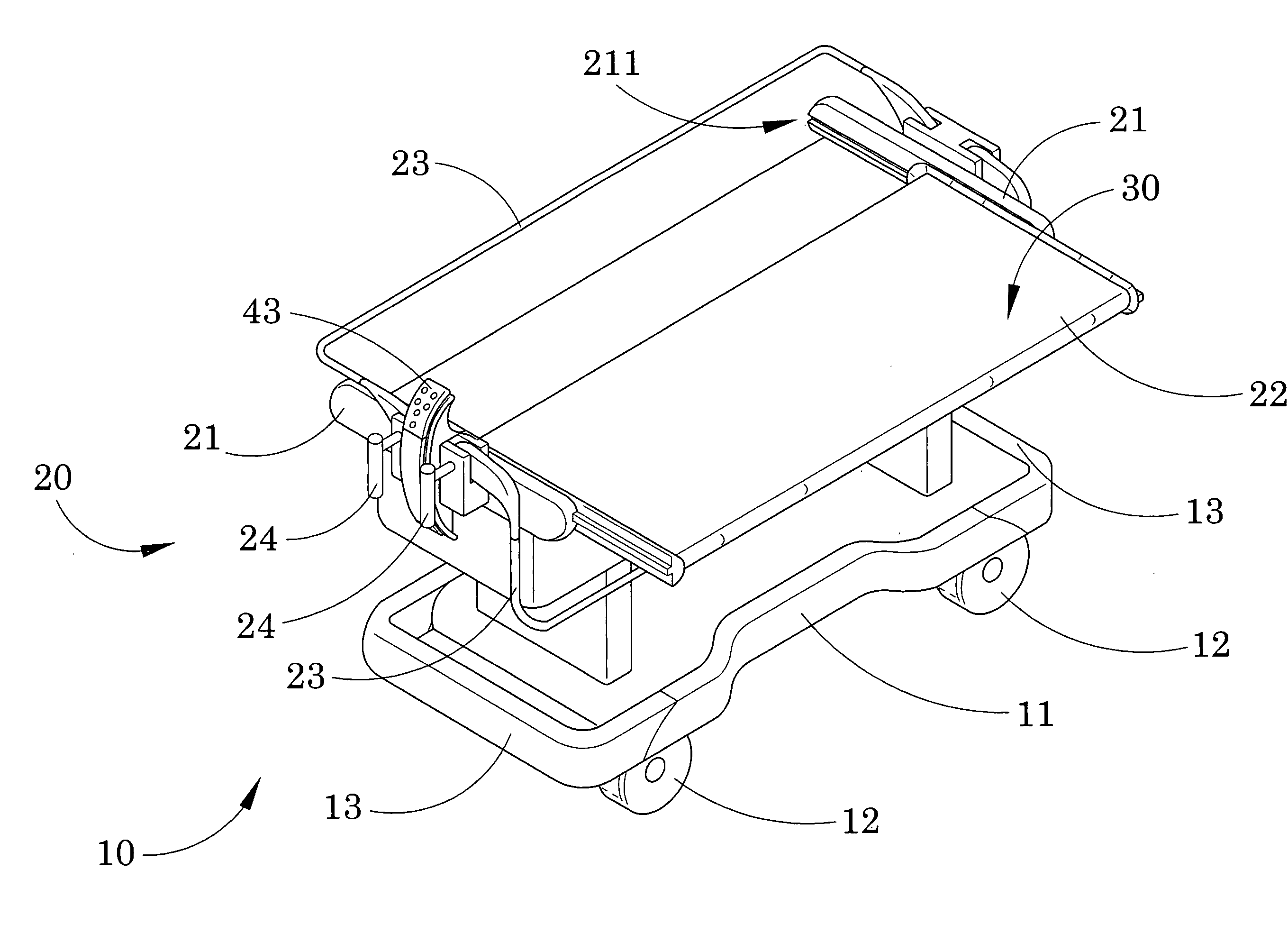
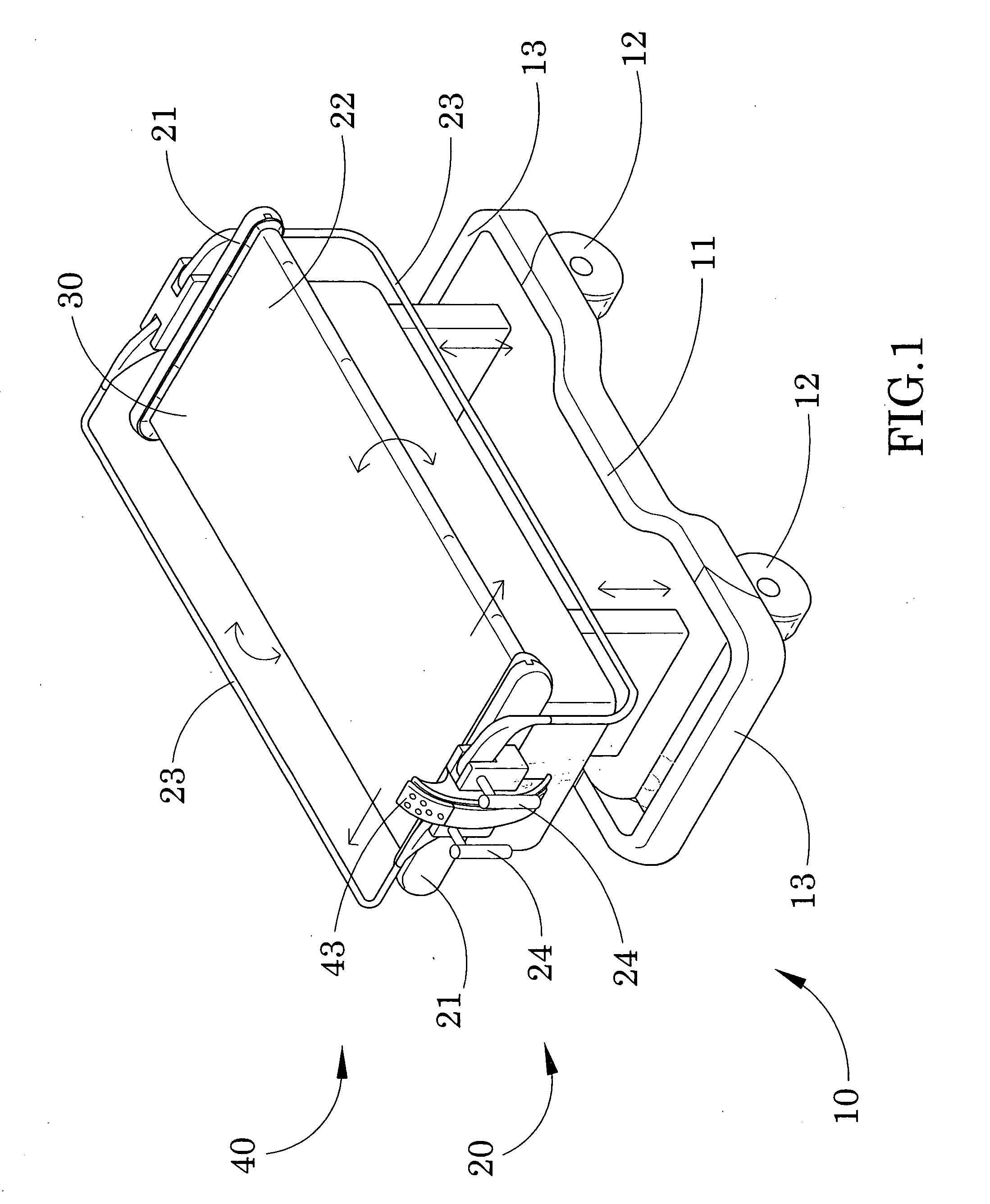
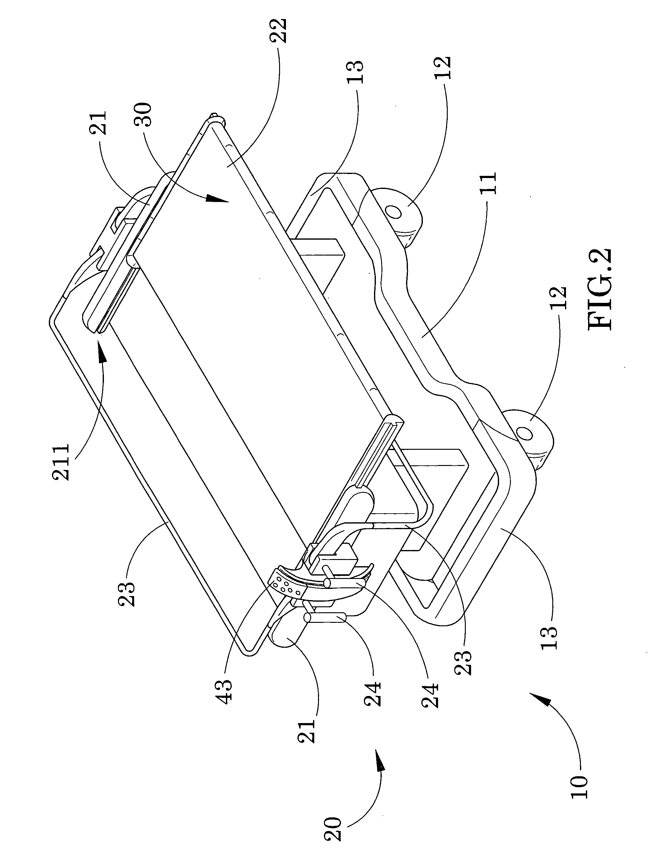
[0034] Referring to FIGS. 1 to 2 of the drawings, an automatic patient transfer system according to a preferred embodiment of the present invention is illustrated, wherein the automatic patient transfer system, which is adapted for efficiently loading, unloading, and transporting a patient from facilities to facilities, comprises a transporting cart 10, a supporting frame 20, and an endless conveyer platform 30.

[0035] As shown in FIGS. 1 to 3, the transporting cart 10 comprises a base stand 11 and a plurality of wheels 12 rotatably mounted underneath the base stand 11, wherein a plurality of wheel locks 13 coupled with the wheels 12 respectively to selectively lock up the wheels 12 in rotating manner.

[0036] The supporting frame 20 is mounted on the transporting cart 10 in vertically movable manner to adjust a height of the supporting frame 20, wherein the supporting frame 20 comprises two spaced apart transverse arms 21 and a supporting bed 22, having a two-side-accessing ability,...


PUM


Abstract

An automatic patient transfer system includes a transporting cart, a supporting frame mounted on the transporting cart in vertically movable manner to adjust a height of the supporting frame, and an endless conveyer platform. The supporting frame includes two spaced apart transverse arms and a supporting bed, having a two-side-accessing ability, slidably mounted between the two transverse arms in a horizontal movable manner, such that the supporting bed is selectively and sidewardly slid with respect to the transporting cart to allow the supporting bed selectively sliding at two opposing sideward directions. The endless conveyer platform is slidably mounted at the supporting bed in loop manner, wherein the conveyer platform is adapted for supporting the patient thereon to selectively load and unload the patient on the supporting bed when the conveyer platform is endlessly rotated at clockwise and counter-clockwise directions.

Description

BACKGROUND OF THE PRESENT INVENTION [0001] 1. Field of Invention [0002] The present invention relates to a mobile cart, and more particularly to an automatic patient transfer system, having two-side accessing ability, adapted for loading, unloading and transporting a patient from facilities to facilities. [0003] 2. Description of Related Arts [0004] Medical attendants always require moving an injured or incapacitated patient from facilities to facilities. Conventionally, the medical attendants use a litter to carry the immobilized patient for transportation. However, the patient's physical condition, size, weight, deformities and physical impairments must be concerned when using litter. An improved transporting cart is used to substitute with the litter for transferring patient. Such transporting cart comprises a platform for supporting the patient thereon and a wheel table mounted underneath the platform in such a manner that when the wheel table is moved next to a suitable bed, th...

Claims


Application Information

Patent Timeline
01 Nov 2007
Publication
US20070251004A1
IPC
A61G7/10
CPC
A61G7/1019; A61G7/1032; A61G2200/32; A61G7/1057; A61G7/1046
Inventors
WANG, XIAO DONG