

Passive grease trap using separator technology
a separator and grease technology, applied in sedimentation settling tanks, liquid displacement, separation processes, etc., can solve the problems of waste to be expelled with grey water, insufficiently preventing grease from going downstream, and causing waste to build up inside the tank
- Summary
- Abstract
- Description
- Claims
- Application Information
AI Technical Summary
Benefits of technology
Problems solved by technology
Method used
Image

Examples
Embodiment Construction
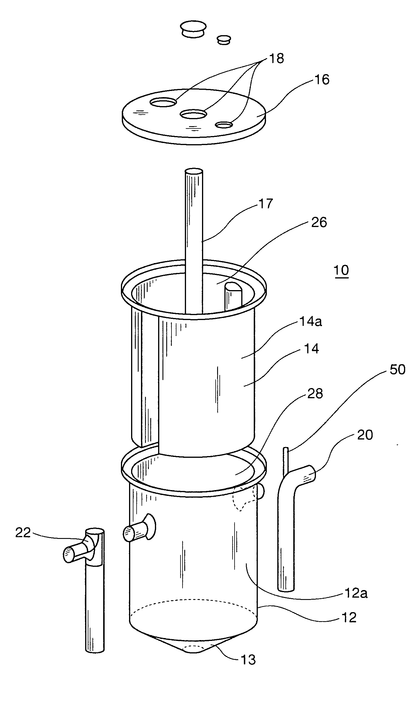
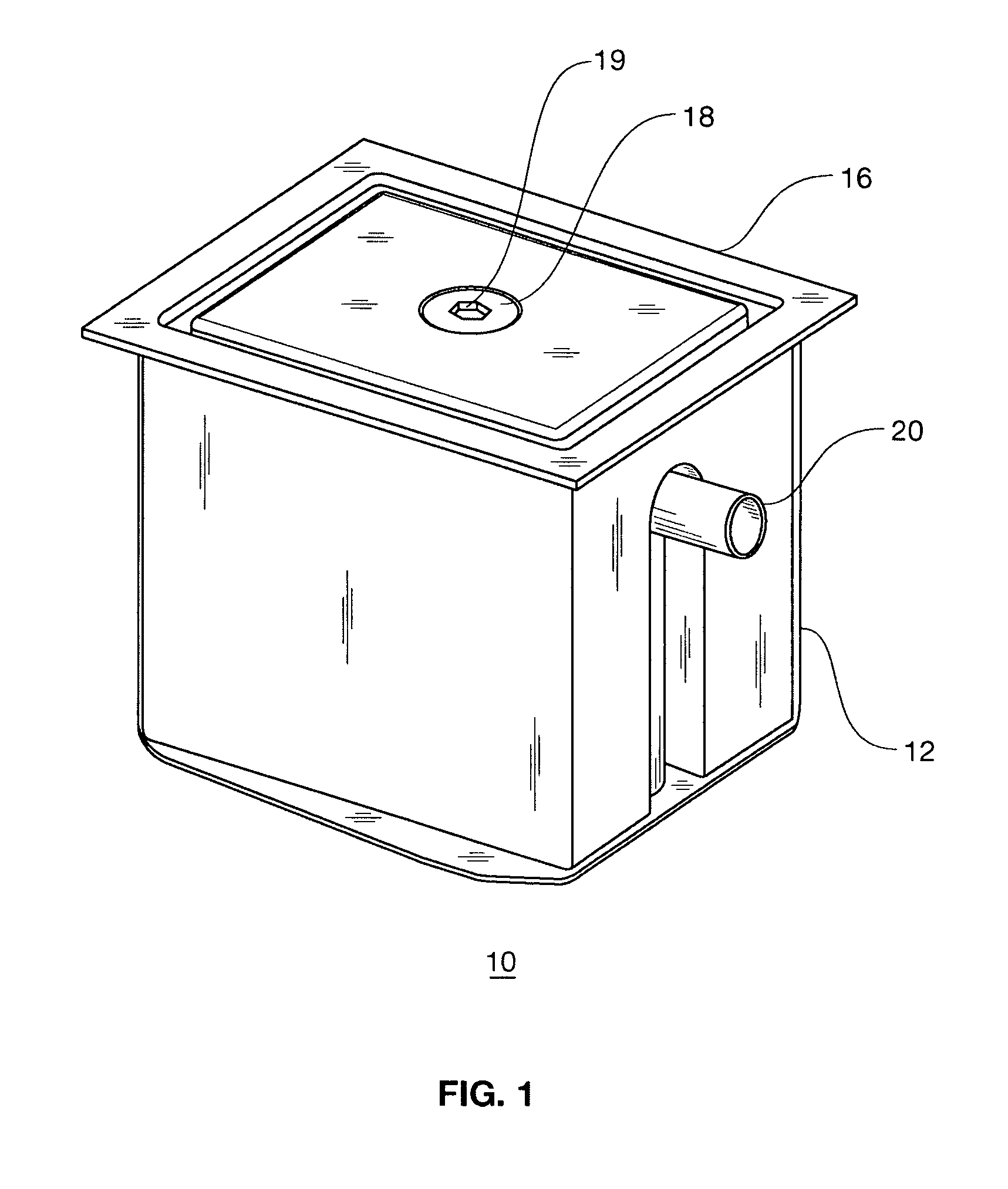
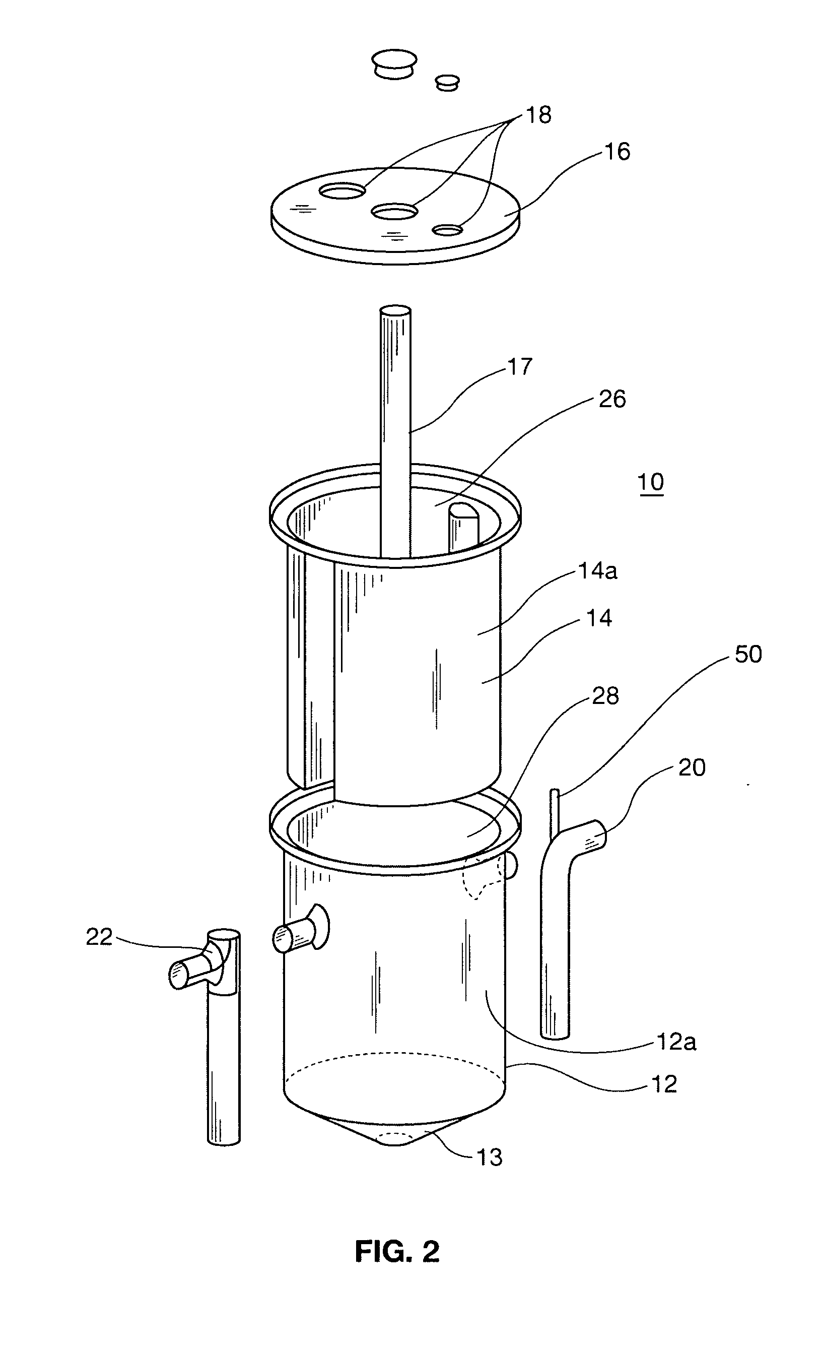
[0021]FIG. 1 shows a grease trap 10 for separating solids and grease from waste water. The grease trap 10 includes an outer tank 12 with a downwardly shaped bottom 13, as seen in FIG. 2. In this embodiment, the downwardly shaped bottom is shaped like an inverted pyramid, but other shapes such as a conical shape, bowl shape, slanted plane, or the like, can be used. Preferably, the lowermost portion is centrally located, but that is not critical. As seen in FIG. 1, an inlet invert 20 is provided for connecting to a waste water source, such as a kitchen sink drain, allowing waste water to flow into the outer tank 12. The grease trap also 10 includes a tank lid 16. The tank lid 16 includes an outlet port 18 provided with a removable closure 19. The outlet port 18 allows for the connection of a pipe through which solids and grease may be sucked out of the grease tank 10. Other outlet ports may be provided to vent gases, selectively remove heavy solids from the downwardly shaped bottom 13...
PUM
| Property | Measurement | Unit |
|---|---|---|
| Diameter | aaaaa | aaaaa |
| Volume | aaaaa | aaaaa |
| Shape | aaaaa | aaaaa |
Abstract
Description
Claims
Application Information