
Method and apparatus for parachute reefing control

Active Publication Date: 2007-11-01
PIONEER AEROSPACE CORP
View PDF55 Cites 18 Cited by
  • Summary
  • Abstract
  • Description
  • Claims
  • Application Information

AI Technical Summary

Benefits of technology

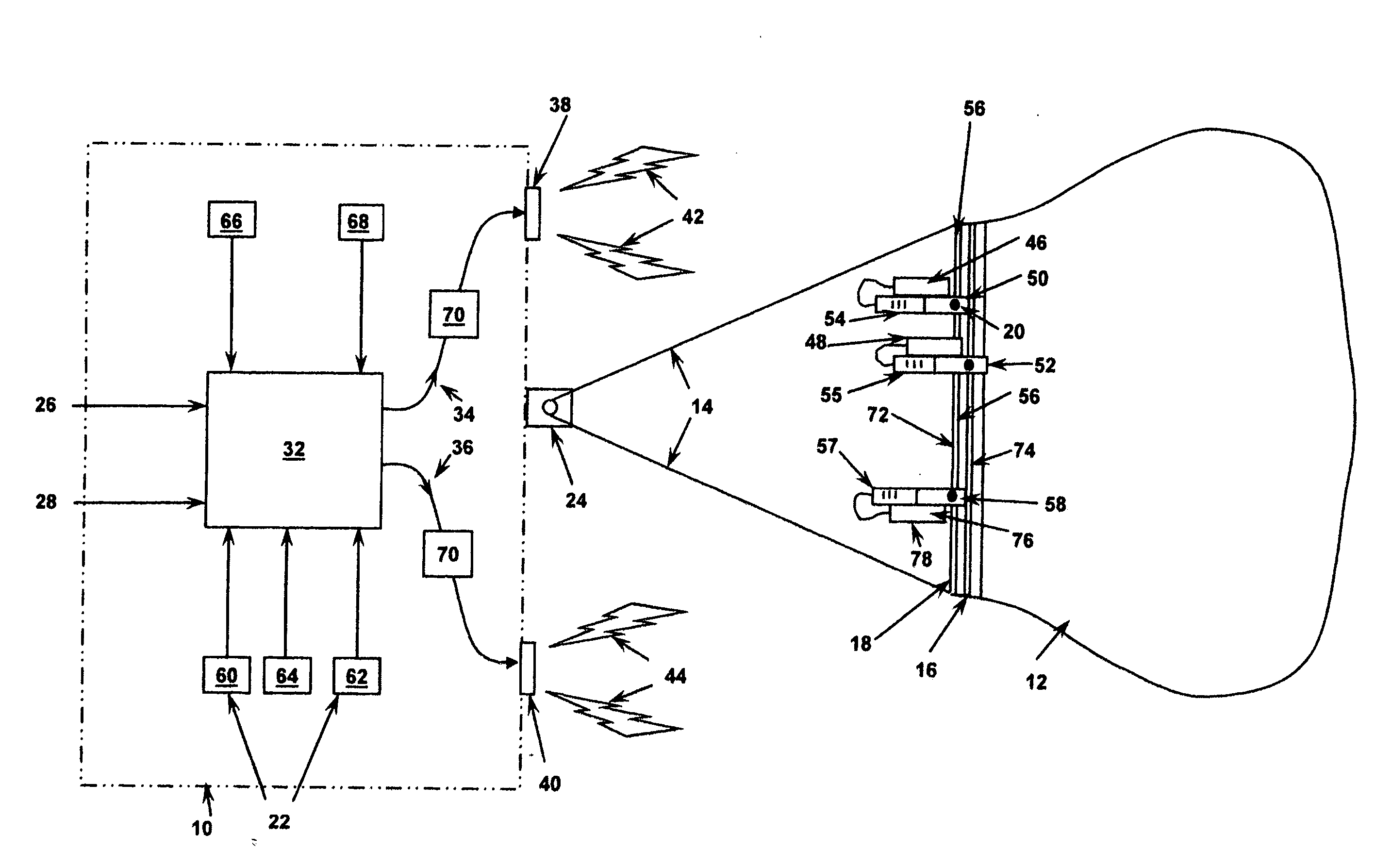
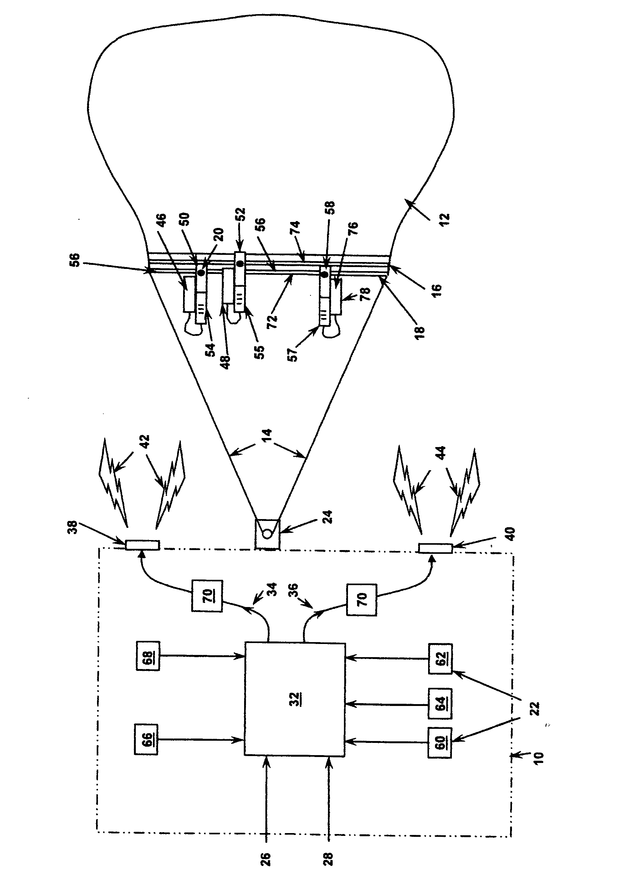
[0012] It should be further appreciated that the method of the present invention can be practiced in such a manner as to not require any direct connection between the payload and the parachute other than through solely the conventional suspension lines extending from the canopy to the payload. This is achieved by monitoring a plurality of parameters with a sensor array which is mounted on the payload. Thereafter a reefing control processor is provided mounted on the payload which continuously receives information on the monitored parameters from the sensor for instantaneously determining a release schedule for the reefing of the parachute canopy. Thereafter at least one wireless signal is transmitted from the payload to the reefing release mechanism mounted adjacent the reefing device at the parachute canopy. This signal is received at the canopy to facilitate actuation of a reefing release mechanism positioned adjacent to the canopy and preferably adjacent to the skirt of the canopy to allow at least partial inflation of the parachute canopy to facilitate control descent thereof with the payload attached thereto. If additional stages of reefing need to be disengaged then additional wireless signals can be generated by the reefing control processor and transmitted to the wireless receiver attached adjacent to the reefing release mechanism. In this manner once the final reefing is disengaged the canopy will be capable of full inflation to efficiently and effectively control airborne descent of the payload.
[0021] It is an object of the apparatus and method for parachute reefing control of the present invention to provide a system which allows for controlling operation of the reefing disengagement means of multiple parachutes which are all connected to the same payload, commonly known as a cluster of parachutes, and, wherein each of these parachutes are disreefed in a coordinated manner to facilitate uniform canopy inflation among all parachutes in the cluster.

Problems solved by technology

However, because the reefing cutters must be installed on the parachute skirt for proper inflation control, these electrical cables can become excessively heavy and risky to the reliability of operation of the parachute due to the length and necessary slack of the fairly heavy electrical cable.

Method used


Image

  • Method and apparatus for parachute reefing control
  • Method and apparatus for parachute reefing control

Examples


Embodiment Construction

[0024] The present invention provides an apparatus for parachute reefing control which includes a vehicle or payload 10 such as a space capsule which includes a parachute 16 attached thereto. Both the payload 10 and the parachute 16 are shown schematically in the figure of the present invention. The parachute 16 includes a canopy 12 which is initially collapsed or packed and is reefed to restrict inflation thereof such that that movement toward the fully inflated state can be controlled. A plurality of suspension lines 14 extend from the canopy 12 of parachute 16 to the payload 10. In one common usage of the apparatus of the present invention is where the payload 10 is a space travel capsule is returning from a mission wherein control of airborne descent thereof is provided by the parachute 16 or a cluster of such parachutes.

[0025] In the present invention a canopy reefing device 18 is shown schematically in the figure extending around the lower surface or edge of the canopy 12 in ...


PUM


Abstract

An apparatus for controlling the drag area growth of a parachute canopy during airborne descent with sensors attached to the payload for facilitating modification of the schedule of release of a parachute canopy reefing mechanism. A control processor is included that can receive and / or calculate a schedule for disengaging the reefing on the parachute. One or more wireless transmitters at the payload transmit the releasing signal from the payload to the reefing mechanism normally located adjacent the parachute canopy. The control processor can also be configured to receive input information from multiple sensors attached to the payload that monitor parameters such as altitude, position, load force, dynamic pressure, time and others to facilitate instantaneous recalculation of the disreefing schedule responsive to such conditions.

Description

BACKGROUND OF THE INVENTION [0001] 1. Field of the Invention [0002] The present invention deals with the field of airborne descent control devices such as parachutes and other gliding wing constructions which are attached to payloads therebeneath such as capsules used for return of individuals or equipment from space travel. Such parachute devices normally need to be reefed in order to restrict or at least control the inflation of the canopy thereof in order to assure a gradual properly formed movement of the canopy from the fully collapsed position within the parachute pack prior to deployment to the fully inflated position. Often multiple stages of such reefing are utilized in order to assure that the canopy gradually moves from the closed position to the fully inflated position to avoid excessive loads or the exposure thereof to improper inflation forces which might damage or otherwise inhibit the full canopy inflation. [0003] Most parachute reefing is accomplished with a continu...

Claims


Application Information

Patent Timeline
IPC IPC(8): B64D17/52
CPCB64D17/343
Inventor SMITH, JOHN J.WITKOWSKI, ALLEN C.
Owner PIONEER AEROSPACE CORP
Learn More