
Sandwiched tubular airbags

a tubular airbag and sandwiched technology, applied in the direction of pedestrian/occupant safety arrangement, vehicular safety arrangment, vehicle components, etc., can solve the problems of chest injury of an occupant, injury to the occupant's body,

Active Publication Date: 2007-11-01
HUNAN UNIV STATE KEY LAB OF ADVANCED DESIGN & MFR FOR VEHICLE BODY
View PDF37 Cites 8 Cited by
  • Summary
  • Abstract
  • Description
  • Claims
  • Application Information

AI Technical Summary

Benefits of technology

"The patent is about an improved structure for safety airbags in vehicles to protect occupants during collisions. The invention relates to the air tube truss, which is a structure made up of one or more bending hollow air tubes. The air tube truss is designed to quickly and fully charge with gas and to be completely deployed in a short time. The charging speed is very quick, so the impact force generated by the gas generator can easily result in injury to the occupant. The invention provides a solution to this problem by incorporating a discharging hole and a pulling belt to help absorb the impact force and protect the occupant from injury. The invention also includes a structure for the air tube truss that can be adapted for different vehicle designs."

Problems solved by technology

Since the charging speed is very quick, the great impact force generated in the forward direction when the airbag begins to expand will probably cause injury to the occupant's body; particularly in the case where the occupant's body is close to the airbag.
In such circumstances, the great impact force can easily result in injury to the chest of an occupant who is very close to the airbag and moving against the expansion direction of the airbag.

Method used


Image

  • Sandwiched tubular airbags
  • Sandwiched tubular airbags
  • Sandwiched tubular airbags

Examples


Embodiment Construction

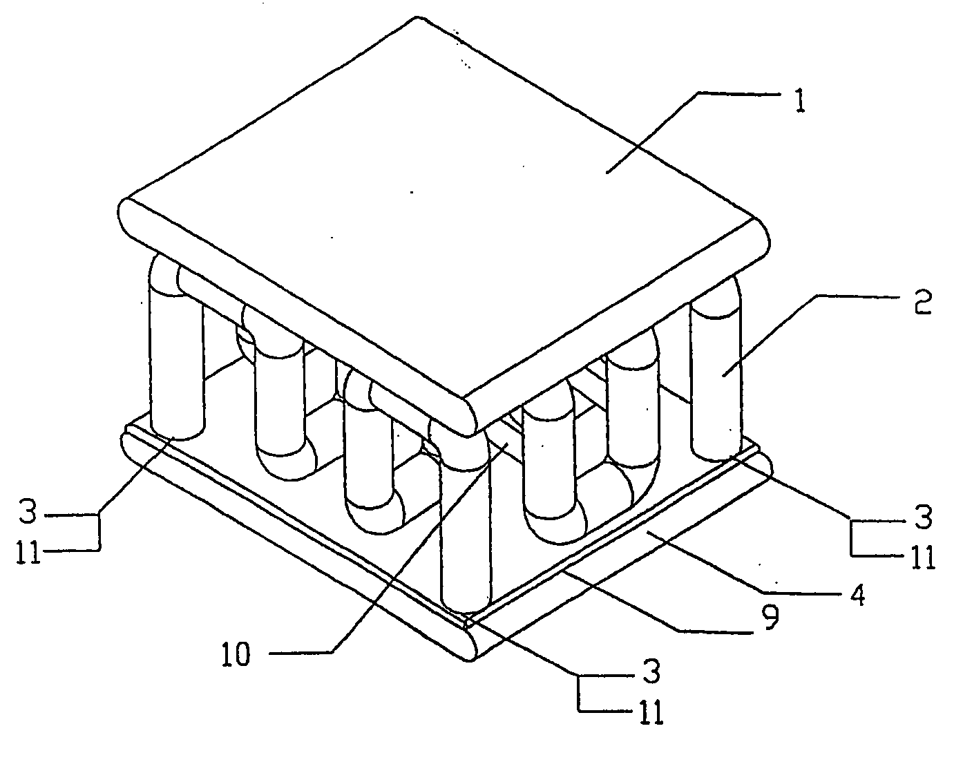
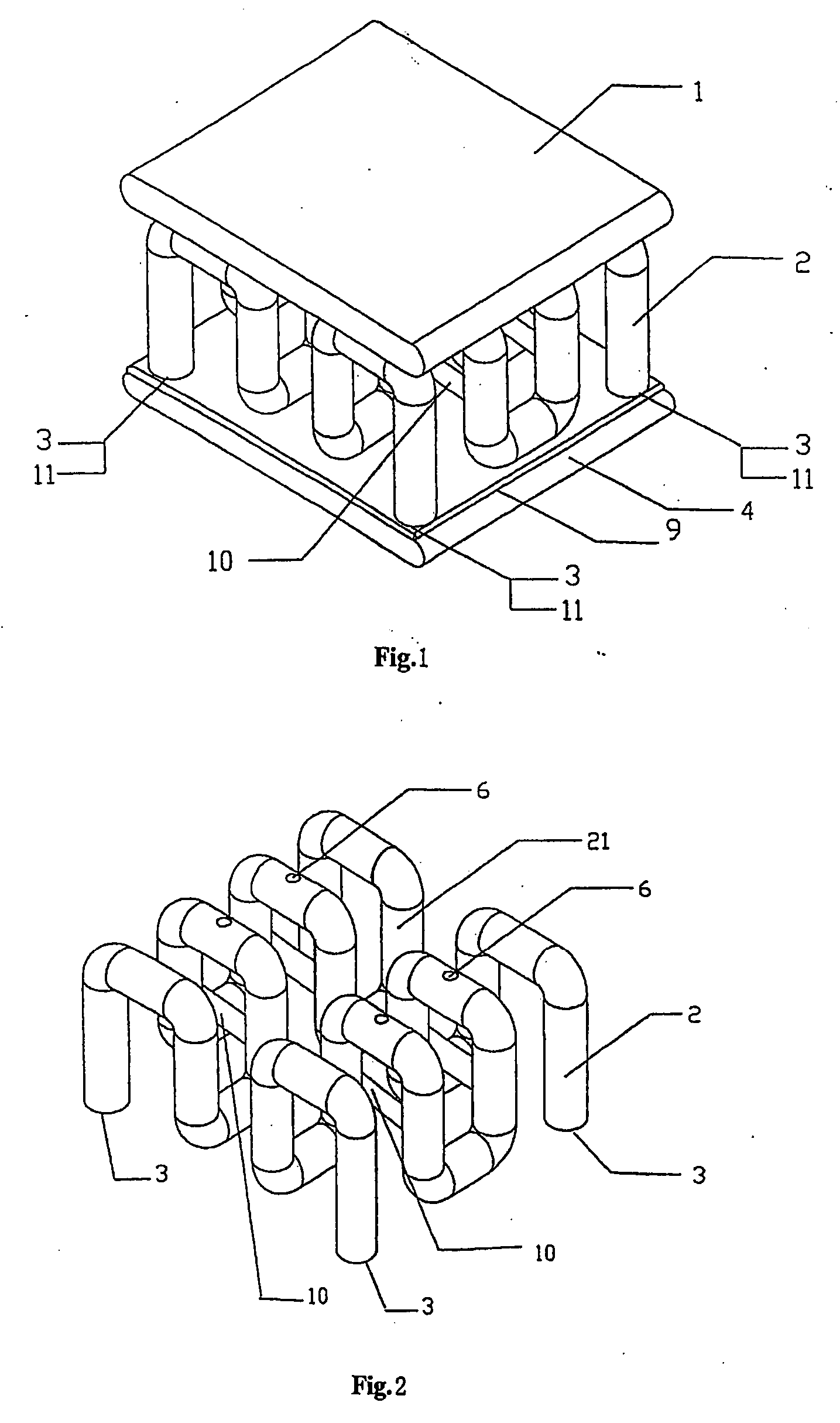
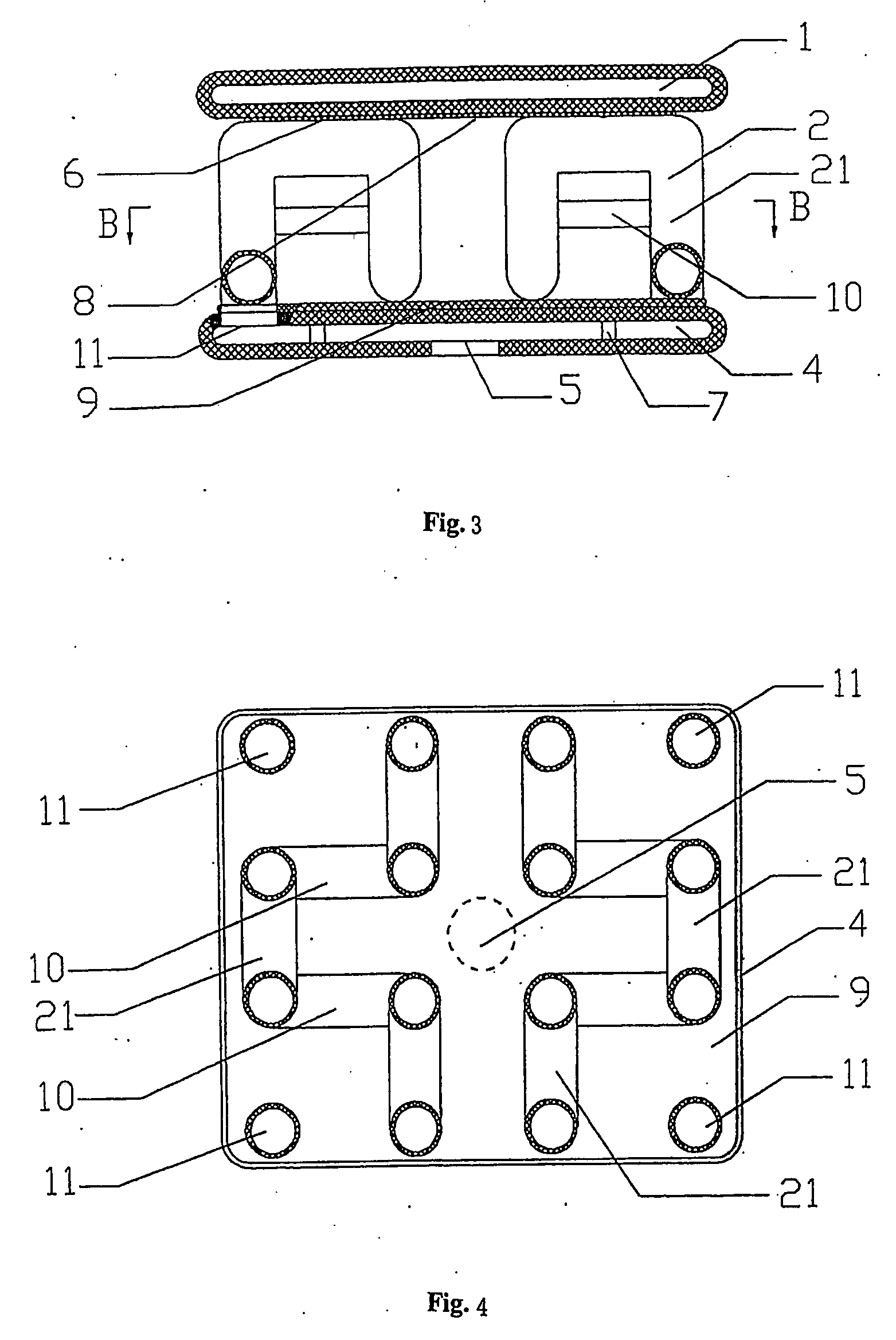
[0029] As shown in FIG. 1 through FIG. 12, example sandwiched tubular airbags constructed in accordance with the teachings of the invention comprise an air tube truss 2 formed by one or more bending hollow air tubes 21, a lower air cushion 4 and an upper air cushion 1. The lower air cushion 4 is provided at the bottom of the air tube truss 2, and the upper air cushion 1 is provided at the top of the air tube truss 2. An inlet opening 5 (see, for example, FIG. 3) is provided on the bottom surface of the lower air cushion 4. The end openings of the hollow air tubes 21 constituting the air tube truss 2 function as charging openings 3 for the air tube truss 2. One or more charging holes 11 (see, for example, FIG. 4) are provided at joints of the lower air cushion 4 with the charging openings 3 of the air tube truss 2. The top of the air tube truss 2 is provided with one or more discharging holes 6 (see, for example, FIG. 2) which communicate with the upper air cushion 1. Seaming connect...


PUM


Abstract

Sandwiched tubular safety airbags are disclosed. An example sandwiched tubular safety airbag comprises an air tube truss (2) formed by a bending hollow air tube (21), a lower air cushion (4) and an upper air cushion (1). The lower air cushion (4) is provided at the bottom of the air tube truss (2), and the upper air cushion (1) is provided on top of the air tube truss (2). An inlet opening (5) is provided on the bottom surface of the lower air cushion (4). The end openings of the hollow air tube (21) of the air tube truss (2) are charging openings (3) of the air tube truss (2). Charging holes (11) are provided at joints of the lower air cushion (4) with the charging openings (3) of the air tube truss (2). The top of the air tube truss (2) is provided with one or more discharging holes (6) communicating with the upper air cushion (1).

Description

RELATED APPLICATION [0001] This patent is a continuation of International Patent Application Serial No. PCT / CN2004 / 001416, which was filed on Dec. 6, 2004 and which is hereby incorporated by reference in its entirety.FIELD OF THE DISCLOSURE [0002] The present disclosure relates generally to safety protection devices, and more specifically to improved structures for safety airbags for use in vehicles to protect occupants during collisions and / or the like. BACKGROUND [0003] Recently, the safety airbag system has found wider and wider application as a constraining device in vehicles to protect the heads of vehicle occupants during an accident such as a collision. All currently available safety airbags employ airbags that can be charged to form a soft air cushion, so as to buffer and absorb energy and hence reduce injuries to occupants. In case of a collision where it is necessary to activate a safety airbag, the airbag is charged with a large amount of gas generated by a gas generator ...

Claims


Application Information

Patent Timeline
Patent Type & Authority Applications(United States)
IPC IPC(8): B60R21/233B60R21/16B60R21/231
CPCB60R2021/23107B60R21/231
Inventor ZHONG, ZHIHUAHE, WEN
Owner HUNAN UNIV STATE KEY LAB OF ADVANCED DESIGN & MFR FOR VEHICLE BODY
Learn More